www.DataSheet4U.com
UTV020
2 Watts, 25 Volts, Class A UHF Television - Band IV & V
GENERAL DESCRIPTION
The UTV 020 is a...
www.DataSheet4U.com
UTV020
2 Watts, 25 Volts, Class A UHF Television - Band IV & V
GENERAL DESCRIPTION
The UTV 020 is a COMMON EMITTER transistor capable of providing 2 Watt Peak, Class A, RF Output Power over the band 470 - 860 MHz. Gold Metalization and Diffused Ballasting are used to provide high reliability and supreme ruggedness.
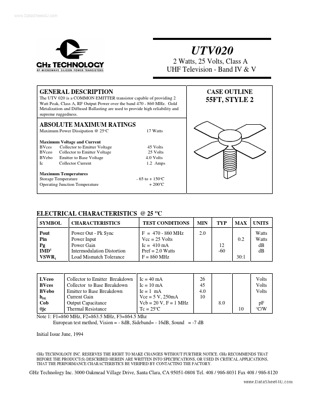
CASE OUTLINE
55FT, STYLE 2
ABSOLUTE MAXIMUM RATINGS
Maximum Power Dissipation @ 25oC Maximum
Voltage and Current BVces Collector to Emitter
Voltage BVceo Collector to Emitter
Voltage BVebo Emitter to Base
Voltage Ic Collector Current Maximum Temperatures Storage Temperature Operating Junction Temperature 17 Watts
45 Volts 25 Volts 4.0 Volts 1.2 Amps - 65 to + 150 oC + 200 oC
ELECTRICAL CHARACTERISTICS @ 25 OC
SYMBOL Pout Pin Pg IMD1 VSWR1 CHARACTERISTICS Power Out - Pk Sync Power Input Power Gain Intermodulation Distortion Load Mismatch Tolerance TEST CONDITIONS F = 470 - 860 MHz Vcc = 25 Volts Ic = 410 mA Pref = 2.0 Watts F = 860 MHz MIN 2.0 0.2 12 -60 30:1 TYP MAX UNITS Watts Watts dB dB
LVceo BVces BVebo hFE Cob θjc
Collector to Emitter Breakdown Collector to Base Breakdown Emitter to Base Breakdown Current Gain Output Capacitance Thermal Resistance
Ic = 40 mA Ic = 10 mA Ie = 1 mA Vce = 5 V, 250mA Vcb = 20 V, F = 1 MHz Tc = 25oC
26 45 4.0 10 8.0 10
Volts Volts Volts pF C/W
o
Note 1: F1=860 MHz, F2=863.5 MHz, F3=864.5 Mhz European test method, Vision = - 8dB, Sideband= - 16dB, Sound = -7 dB Initial Issue June, 1994
GHz TECHNOLOGY...