UTC UT134F/G
TRIACS
DESCRIPTION
Glass passivated triacs in a plastic envelope, intended for use in applications requirin...
UTC UT134F/G
TRIACS
DESCRIPTION
Glass passivated triacs in a plastic envelope, intended for use in applications requiring highbidirectional transient and blocking
voltage capability and high thermal cycling performance. Typical applications include motor control, industrial and domestic lighting, heating and static switching.
TRIAC
1
SYMBOL
MT2
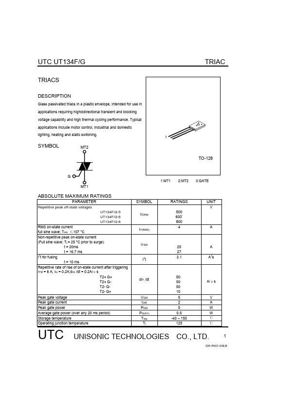
TO-126
G
1:MT1 2:MT2 3:GATE
MT1
ABSOLUTE MAXIMUM RATINGS
PARAMETER
Repetitive peak off-state
voltages UT134F/G-5 UT134F/G-6 UT134F/G-8
www.DataSheet4U.com
SYMBOL
VDRM
RATINGS
500 600* 800 4
UNIT
V
RMS on-state current full sine wave; Tmb ≤107 °C Non-repetitive peak on-state current (Full sine wave; Tj = 25 °C prior to surge) t = 20ms t = 16.7 ms I2t for fusing t = 10 ms Repetitive rate of rise of on-state current after triggering ITM = 6 A; IG = 0.2A;dIG /dt = 0.2A/μs T2+ G+ T2+ GT2- GT2- G+ Peak gate
voltage Peak gate current Peak gate power Average gate power (over any 20 ms period) Storage temperature Operating junction temperature
IT(RMS)
A
ITSM
I2t
25 27 3.1
A A2s
dIT /dt
50 50 50 10 5 2 5 0.5 -40 ~ 150 125
A/μs
VGM IGM PGM PG(AV) Tstg Tj
V A W W ℃ ℃
UTC
UNISONIC TECHNOLOGIES CO., LTD.
1
QW-R401-008,B
UTC UT134F/G
TRIAC
*Although not recommended, off-state
voltages up to 800V may be applied without damage, but the traic may switch to the on-state. The rate of rise of current should not exceed 3A/µs.
THERMAL RESISTANCES
PARAMETER
Thermal resistance Junction to mounting base Full cycle Half cycle Therm...