Filter Specification
tfs400f.doc
version 1.2
02.11.2000
VI TELEFILTER
Filter Specification
TFS 400 F
1/5
Measurement condition
Ambient...
Description
tfs400f.doc
version 1.2
02.11.2000
VI TELEFILTER
Filter Specification
TFS 400 F
1/5
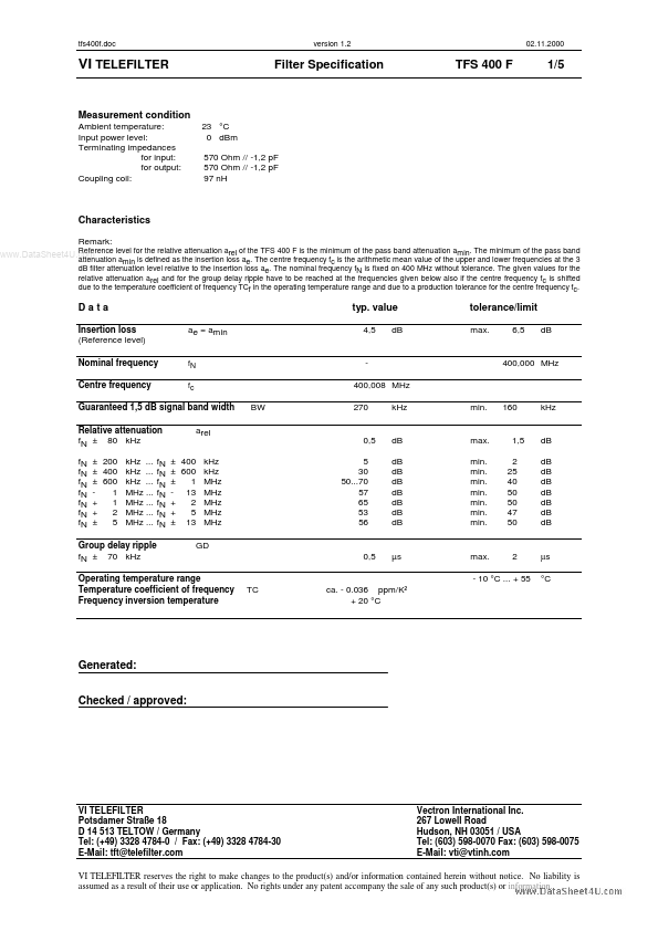
Measurement condition
Ambient temperature: Input power level: Terminating impedances for input: for output: Coupling coil: 23 °C 0 dBm 570 Ohm // -1,2 pF 570 Ohm // -1,2 pF 97 nH
Characteristics
Remark: Reference level for the relative attenuation arel of the TFS 400 F is the minimum of the pass band attenuation amin. The minimum of the pass band www.DataSheet4U.com
attenuation amin is defined as the insertion loss ae. The centre frequency fc is the arithmetic mean value of the upper and lower frequencies at the 3 dB filter attenuation level relative to the insertion loss ae. The nominal frequency fN is fixed on 400 MHz without tolerance. The given values for the relative attenuation arel and for the group delay ripple have to be reached at the frequencies given below also if the centre frequency fc is shifted due to the temperature coefficient of frequency TCf in the operating temperature range and due to a production tolerance for the centre frequency fc.
Data
Insertion loss (Reference level) Nominal frequency Centre frequency ae = amin
typ. value
4,5 dB
tolerance/limit
max. 6,5 dB
fN fc
400,008 MHz BW 270 kHz min.
400,000 MHz
Guaranteed 1,5 dB signal band width Relative attenuation fN ± 80 kHz fN fN fN fN fN fN fN arel
160
kHz
0,5 5 30 50...70 57 65 53 56
dB dB dB dB dB dB dB dB
max. min. min. min. min. min. min. min.
1,5 2 25 40 50 50 47 50
dB dB dB dB dB dB dB dB
±...
Similar Datasheet