IRFBC40AS, SiHFBC40AS
Vishay Siliconix
Power MOSFET
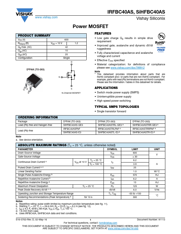
PRODUCT SUMMARY
VDS (V) RDS(on) () Qg (Max.) (nC)
600 VGS = 10 V...
IRFBC40AS, SiHFBC40AS
Vishay Siliconix
Power
MOSFET
PRODUCT SUMMARY
VDS (V) RDS(on) () Qg (Max.) (nC)
600 VGS = 10 V
42
Qgs (nC)
10
Qgd (nC)
20
Configuration
Single
D
D2PAK (TO-263)
1.2
G
GD S
ORDERING INFORMATION
Package Lead (Pb)-free and Halogen-free
Lead (Pb)-free
Note a. See device orientation.
S N-Channel
MOSFET
D2PAK (TO-263) SiHFBC40AS-GE3 IRFBC40ASPbF SiHFBC40AS-E3
FEATURES Halogen-free According to IEC 61249-2-21
Definition Low Gate Charge Qg results in Simple Drive
Requirement Improved Gate, Avalanche and Dynamic dV/dt
Ruggedness Fully Characterized Capacitance and Avalanche
Voltage
and Current Effective Coss Specified Compliant to RoHS Directive 2002/95/EC
APPLICATIONS Switch Mode Power Supply (SMPS) Uninterruptible Power Supply High Speed Power Switching
TYPICAL SMPS TOPOLOGIES Single Transistor Forward
D2PAK (TO-263) SiHFBC40ASTRL-GE3a IRFBC40ASTRLPbFa SiHFBC40ASTL-E3a
D2PAK (TO-263) SiHFBC40ASTRR-GE3a IRFBC40ASTRRPbFa SiHFBC40ASTR-E3a
ABSOLUTE MAXIMUM RATINGS (TC = 25 °C, unless otherwise noted)
PARAMETER
SYMBOL
Drain-Source
Voltage Gate-Source
Voltage
Continuous Drain Currente
Pulsed Drain Currenta, e Linear Derating Factor Single Pulse Avalanche Energyb Repetitive Avalanche Currenta Repetitive Avalanche Energya Maximum Power Dissipation Peak Diode Recovery dV/dtc, e
VGS at 10 V
TC = 25 °C TC = 100 °C
TC = 25 °C
VDS VGS
ID
IDM
EAS IAR EAR PD dV/dt
Operating Junction and Storage Temperature Range Soldering Recomme...