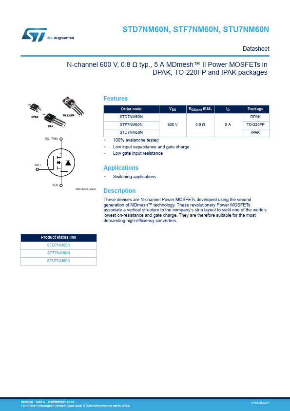
STD7NM60N, STF7NM60N STP7NM60N, STU7NM60N
N-channel 600 V, 4.7 A, DPAK, TO-220FP, TO-220, IPAK second generation MDmesh™...
STD7NM60N, STF7NM60N STP7NM60N, STU7NM60N
N-channel 600 V, 4.7 A, DPAK, TO-220FP, TO-220, IPAK second generation MDmesh™ Power
MOSFET
Preliminary data
Features
Type STD7NM60N STF7NM60N STP7NM60N STU7NM60N
■ ■ ■
VDSS @ TJmax
RDS(on) max
ID
Pw
2
3
3 1 2
650 V
< 0.9 Ω
4.7 A
45 W 20 W 45 W 45 W
1
IPAK
TO-220
100% avalanche tested Low input capacitance and gate charge Low gate input resistance
3 1
3 2
DPAK
1
TO-220FP
Application
■
Switching applications
Figure 1.
Internal schematic diagram
Description
This second generation of MDmesh™ technology, applies the benefits of the multiple drain process to STMicroelectronics’ well-known PowerMESH™ horizontal layout structure. The resulting product offers improved on-resistance, low gate charge, high dv/dt capability and excellent avalanche www.DataSheet4U.com characteristics.
$
'
3
!-V
Table 1.
Device summary
Marking Package DPAK TO-220FP 7NM60N TO-220 IPAK Packaging Tape and reel Tube Tube Tube
Order codes STD7NM60N STF7NM60N STP7NM60N STU7NM60N
October 2009
Doc ID 16472 Rev 1
1/14
www.st.com 14
This is preliminary information on a new product now in development or undergoing evaluation. Details are subject to change without notice.
Contents
STD7NM60N, STF7NM60N, STP7NM60N, STU7NM60N
Contents
1 2 3 4 5 6 Electrical ratings . . . . . . . . . . . . . . . . . . . . . . . . . . . . . . . . . . . . . . . . . . . . 3 Electrical characteristics . . . . . . . . . . . . . . . . . . . . . . . . ...