RSS120N03
Transistors
Switching (30V, 12A)
RSS120N03
zFeatures 1) Low on-resistance. www.DataSheet4U.com 2) Built-in G-...
RSS120N03
Transistors
Switching (30V, 12A)
RSS120N03
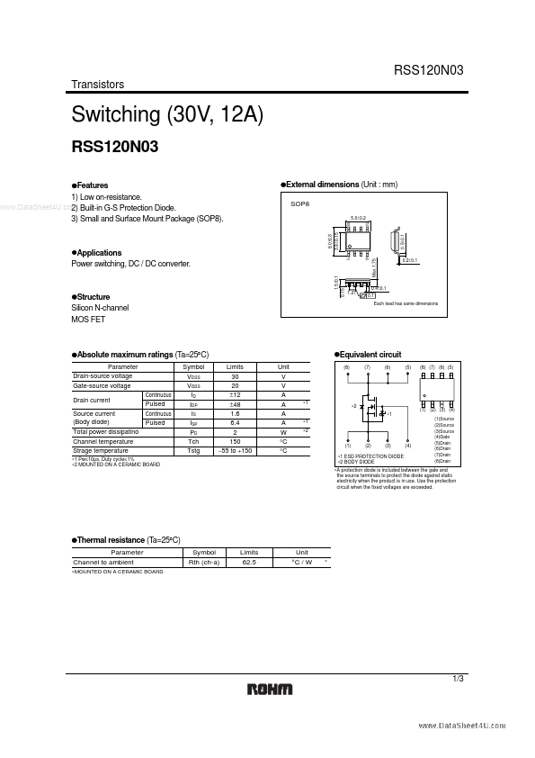
zFeatures 1) Low on-resistance. www.DataSheet4U.com 2) Built-in G-S Protection Diode. 3) Small and Surface Mount Package (SOP8). zExternal dimensions (Unit : mm)
SOP8
5.0±0.2
(5) (8)
6.0±0.3 3.9±0.15
1.5±0.1 0.15
zStructure Silicon N-channel MOS FET
1.27
0.4±0.1 0.1 Each lead has same dimensions
zAbsolute maximum ratings (Ta=25°C)
Parameter Drain-source
voltage Gate-source
voltage Drain current Source current (Body diode) Total power dissipatino Channel temperature Strage temperature
∗1 Pw≤10µs, Duty cycle≤1% ∗2 MOUNTED ON A CERAMIC BOARD
zEquivalent circuit
Limits 30 20 ±12 ±48 1.6 6.4 2 150 −55 to +150 Unit V V A A A A W °C °C
(8) (7) (6) (5) (8) (7) (6) (5)
Continuous Pulsed Continuous Pulsed
Symbol VDSS VGSS ID IDP IS ISP PD Tch Tstg
∗1 ∗1 ∗2
(1)
∗2 ∗1
Max.1.75
zApplications Power switching, DC / DC converter.
0.5±0.1
(1) (4)
0.2±0.1
(1) (2) (3) (4)
(1)Source (2)Source (3)Source (4)Gate (5)Drain (6)Drain (7)Drain (8)Drain
(2)
(3)
(4)
∗1 ESD PROTECTION DIODE ∗2 BODY DIODE
∗A protection diode is included between the gate and the source terminals to protect the diode against static electricity when the product is in use. Use the protection circuit when the fixed
voltages are exceeded.
zThermal resistance (Ta=25°C)
Parameter Channel to ambient
∗MOUNTED ON A CERAMIC BOARD
Symbol Rth (ch-a)
Limits 62.5
Unit °C / W
∗
1/3
RSS120N03
Transistors
zElectrical characteristics (Ta=25°C)
Parameter Symbol I...