REMEC
m o Hybrid Amplifiers c . Low Noise Figure U 4 t e Electrical Specifications : e h S a t a D . w w w
(1)
1930 - ...
REMEC
m o Hybrid
Amplifiers c . Low Noise Figure U 4 t e Electrical Specifications : e h S a t a D . w w w
(1)
1930 - 1990 MHz
Parameter
Specification Limit
Units °C MHz dB dB Max dB Max p-p dB Min Max Max dBm Min
QBH-8709
Temperature Frequency Range Small Signal Gain Gain vs. Temperature Gain Flatness Reverse Isolation VSWR Input Output 1 dB Compression Output Intercept Point 3rd Order 2nd Order Noise Figure DC Power @ 12 Vdc ± 1% Gain vs. Vdc Housing
Notes: 1. Specifications are guaranteed when tested in a 50 Ohm system. Specifications indicated as typical are not guaranteed.
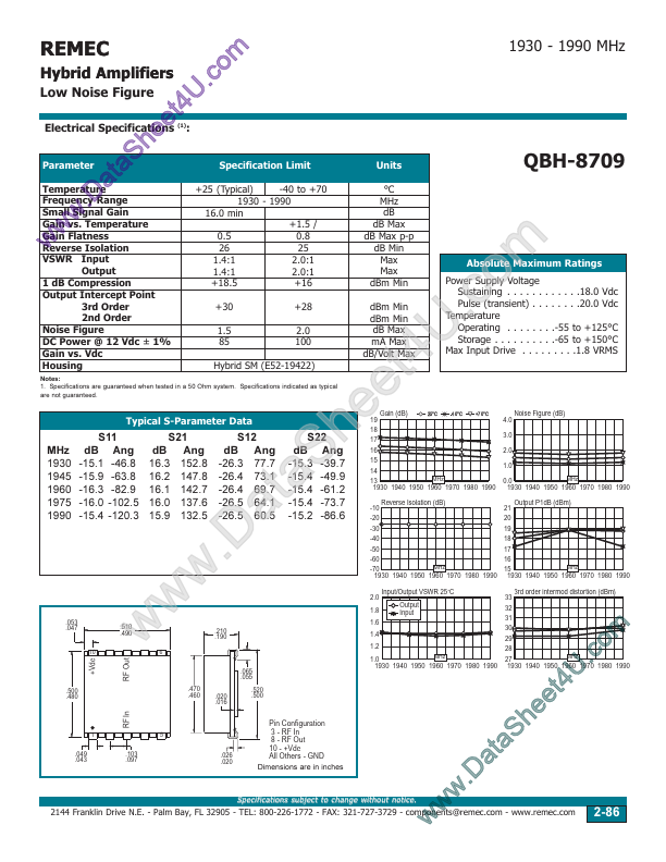
Typical S-Parameter Data
MHz 1930 1945 1960 1975 1990
S11 dB Ang -15.1 -46.8 -15.9 -63.8 -16.3 -82.9 -16.0 -102.5 -15.4 -120.3
.053 .047
.510 .490
10
m o .c U 4 t e e h S a t a .D w w w
+30 1.5 85 +28 2.0 100 dBm Min dBm Min dB Max mA Max dB/Volt Max Hybrid SM (E52-19422)
19 18 17 16 15 14 Gain (dB)
25°C -40°C +70°C
+25 (Typical) -40 to +70 1930 - 1990 16.0 min +1.5 / 0.5 0.8 26 25 1.4:1 2.0:1 1.4:1 2.0:1 +18.5 +16
Absolute Maximum Ratings
Power Supply
Voltage Sustaining . . . . . . . . . . . .18.0 Vdc Pulse (transient) . . . . . . . .20.0 Vdc Temperature Operating . . . . . . . .-55 to +125°C Storage . . . . . . . . . .-65 to +150°C Max Input Drive . . . . . . . . .1.8 VRMS
4.0 3.0 2.0 1.0
Noise Figure (dB)
S21 dB Ang 16.3 152.8 16.2 147.8 16.1 142.7 16.0 137.6 15.9 132.5
S12 dB Ang -26.3 77.7 -26.4 73.1 -26.4 69.7 -26.5 64.1 -26.5 60.5
S22 dB Ang -15.3 -39.7 -15.4 -49.9 -15.4 -6...