DatasheetsPDF.com
P6KE-G
Part Number
P6KE-G
Manufacturer
Comchip Technology
Description
600W Transient Voltage Suppressor
Published
Feb 25, 2011
Datasheet
P6KE-G
PDF File
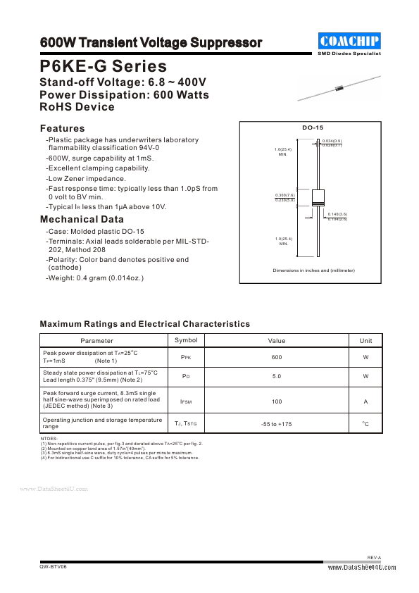
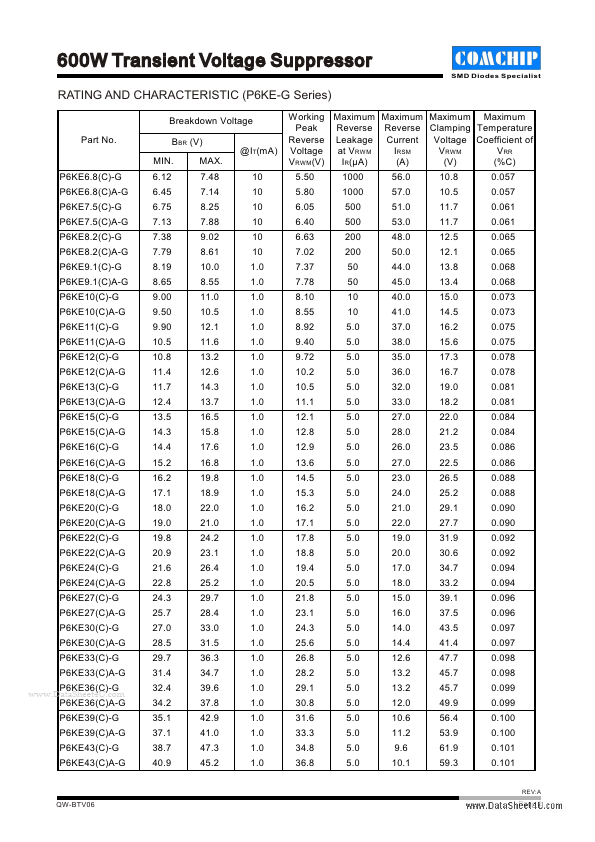
Features
-Plastic package has underwriters laboratory flammability classification 94V-0 -600W, surge capability at 1mS.-Excellent clamping capability.-Low
Zener
impedance.-Fast response time: typically less than 1.0pS from 0 volt to BV min.-Typical I R le...
Similar Datasheet
Since 2006. D4U Semicon,
Electronic Components Datasheet Search Site. (
Privacy Policy & Contact
)