NTMC1300R2
Power MOSFET 3 Amps, 30 Volts
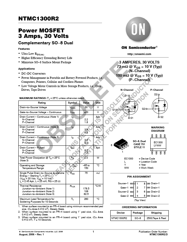
Complementary SO−8 Dual
Features
• Ultra Low RDS(on) • Higher Efficiency Exten...
NTMC1300R2
Power
MOSFET 3 Amps, 30 Volts
Complementary SO−8 Dual
Features
Ultra Low RDS(on) Higher Efficiency Extending Battery Life Miniature SO−8 Surface Mount Package
Applications
DC−DC Converters Power Management in Portable and Battery Powered Products, i.e.:
Computers, Printers, Cellular and Cordless Phones
Low
Voltage Motor Controls in Mass Storage Products, i.e.: Disk
Drives, Tape Drives
MAXIMUM RATINGS (TJ = 25°C unless otherwise noted)
Rating
Symbol
Value
Unit
Drain−to−Source
Voltage Gate−to−Source
Voltage − Continuous Drain Current − Continuous (Note 1)
N−Channel P−Channel
VDSS VGS ID
30 V ±20 V
Adc 2.2 1.8
Drain Current − Continuous (Note 2) N−Channel P−Channel
ID Adc 2.8 2.3
Drain Current − Continuous (Note 3) N−Channel P−Channel
ID
Adc 3.6
3.0
Drain Current − Pulsed N−Channel P−Channel
IDM Apk 8.5 7.0
Total Power Dissipation @ TA = 25°C (Note 3)
PD 2.0 W
Operating and Storage Temperature Range
TJ, Tstg
−65 to 150
°C
Single Pulse Drain−to−Source Avalanche Energy − Starting TJ = 25°C (VDD = 20 Vdc, VGS = 10 Vdc, IL = 2.45 Apk, L = 25 mH, RG = 25 W) Thermal Resistance
Junction−to−Ambient (Note 1) Junction−to−Ambient (Note 2) Junction−to−Ambient (Note 3)
EAS RqJA
75 mJ
178.5 106 62.5
°C/W
Maximum Lead Temperature for Soldering Purposes for 10 Seconds
TL 260 °C
1. When surface mounted to an FR−4 board using minimum recommended pad size, (Cu Area 0.412 in2), Steady State.
2. When surface mounted to an FR−4 board using 1″ pad ...