Q-Band 2-Stage Power Amplifier
PRELIMINARY
Notice : This is not a final specification Some parametric limits are subject to change.
MITSUBISHI SEMICON...
Description
PRELIMINARY
Notice : This is not a final specification Some parametric limits are subject to change.
MITSUBISHI SEMICONDUCTOR
MGFC5214
Q-Band 2-Stage Power Amplifier
DESCRIPTION
The MGFC5214 is a GaAs MMIC chip especially designed for 37.0 ~ 40.0 GHz band High Power Amplifier (HPA) .
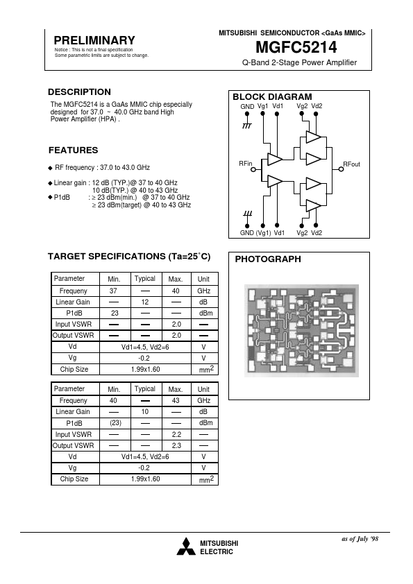
BLOCK DIAGRAM
GND Vg1 Vd1 Vg2 Vd2
FEATURES
RF frequency : 37.0 to 43.0 GHz Linear gain : 12 dB (TYP.)@ 37 to 40 GHz 10 dB(TYP.) @ 40 to 43 GHz P1dB : ≥ 23 dBm(min.) @ 37 to 40 GHz ≥ 23 dBm(target) @ 40 to 43 GHz
RFin RFout
GND (Vg1) Vd1
Vg2 Vd2
TARGET SPECIFICATIONS (Ta=25˚C)
Parameter Frequeny Linear Gain P1dB Input VSWR Output VSWR Vd Vg Chip Size Parameter Frequeny Linear Gain P1dB Input VSWR Output VSWR Vd Vg Chip Size Vd1=4.5, Vd2=6 -0.2 1.99x1.60 (23) 2.2 2.3 V V mm2 Min. 40 10 Vd1=4.5, Vd2=6 -0.2 1.99x1.60 Typical Max. 43 23 2.0 2.0 V V mm2 Unit GHz dB dBm Min. 37 12 Typical Max. 40 Unit GHz dB dBm
PHOTOGRAPH
MITSUBISHI ELECTRIC
as of July '98
PRELIMINARY
Notice : This is not a final specification Some parametric limits are subject to change.
MITSUBISHI SEMICONDUCTOR
MGFC5214
Q-Band 2-Stage Power Amplifier
DIE SIZE AND BOND PAD LOCATION(UNIT : µM)
X=1.99 mm Y=1.60 mm Bond Pad Dimension=0.07 x 0.15 mm2 (RF) 0.10 x 0.10 mm2 (DC)
(680.0, 1470.0) (1555.0, 1470.0) (505.0, 1470.0) (1165.0, 1470.0) (125.0, 1470.0)
(105.0, 800.0)
(1885.0, 800.0)
(125.0, 130.0) (0, 0) (505.0, 130.0) (1165.0, 130.0) (680.0, 130.0) (1555.0, 130.0)
GND
Vg1 Vd1
Vg2
Vd2
RFi...
Similar Datasheet