M50LPW012
2 Mbit (256Kb x8, Boot Block) 3V Supply Low Pin Count Flash Memory
PRELIMINARY DATA
s
SUPPLY VOLTAGE – VCC = ...
M50LPW012
2 Mbit (256Kb x8, Boot Block) 3V Supply Low Pin Count Flash Memory
PRELIMINARY DATA
s
SUPPLY
VOLTAGE – VCC = 3V to 3.6V for Program, Erase and Read Operations
s
– VPP = 12V for Fast Program and Fast Erase LOW PIN COUNT (LPC) – Standard Interface for embedded operation with PC Chipsets that are without automapping memory features
s
ADDRESS/ADDRESS MULTIPLEXED (A/A MUX) – Interface for programming equipment compatibility
PLCC32 (K)
s
LOW PIN COUNT (LPC) HARDWARE INTERFACE MODE – 5 Signal Communication Interface supporting Read and Write Operations – Hardware Write Protect Pins for Block Protection – Register Based Read and Write Protection – 5 Additional General Purpose Inputs for platform design flexibility – Synchronized with 33MHz PCI clock
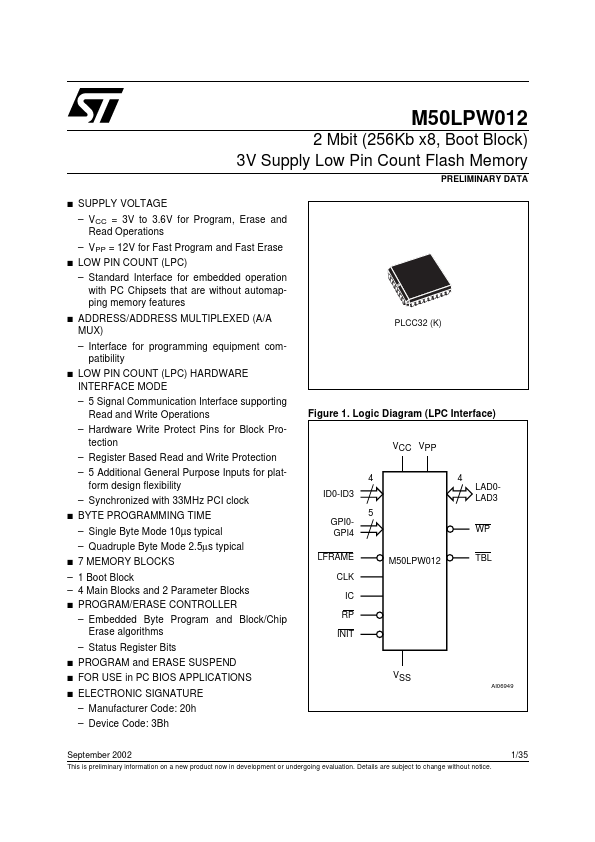
4 ID0-ID3 5 GPI0GPI4 LFRAME CLK IC RP INIT M50LPW012 WP TBL 4 LAD0LAD3
Figure 1. Logic Diagram (LPC Interface)
VCC VPP
s
BYTE PROGRAMMING TIME – Single Byte Mode 10µs typical – Quadruple Byte Mode 2.5µs typical
s
7 MEMORY BLOCKS
– 1 Boot Block – 4 Main Blocks and 2 Parameter Blocks s PROGRAM/ERASE CONTROLLER – Embedded Byte Program and Block/Chip Erase algorithms – Status Register Bits
s s s
PROGRAM and ERASE SUSPEND FOR USE in PC BIOS APPLICATIONS ELECTRONIC SIGNATURE – Manufacturer Code: 20h – Device Code: 3Bh
VSS
AI06949
September 2002
This is preliminary information on a new product now in development or undergoing evaluation. Details are subject to change without notice.
1/35
M50LPW012
Figure 2. Logic Diag...