M50FW002
2 Mbit (256Kb x8, Boot Block) 3V Supply Firmware Hub Flash Memory
PRELIMINARY DATA
FEATURES SUMMARY s SUPPLY V...
M50FW002
2 Mbit (256Kb x8, Boot Block) 3V Supply Firmware Hub Flash Memory
PRELIMINARY DATA
FEATURES SUMMARY s SUPPLY
VOLTAGE – VCC = 3 V to 3.6 V for Program, Erase and Read Operations – VPP = 12 V for Fast Program and Fast Erase (optional)
s
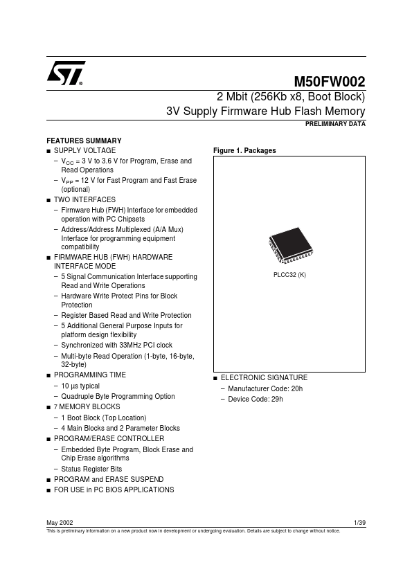
Figure 1. Packages
TWO INTERFACES – Firmware Hub (FWH) Interface for embedded operation with PC Chipsets – Address/Address Multiplexed (A/A Mux) Interface for programming equipment compatibility
s
FIRMWARE HUB (FWH) HARDWARE INTERFACE MODE – 5 Signal Communication Interface supporting Read and Write Operations – Hardware Write Protect Pins for Block Protection – Register Based Read and Write Protection – 5 Additional General Purpose Inputs for platform design flexibility – Synchronized with 33MHz PCI clock – Multi-byte Read Operation (1-byte, 16-byte, 32-byte)
PLCC32 (K)
s
PROGRAMMING TIME – 10 µs typical – Quadruple Byte Programming Option
s
ELECTRONIC SIGNATURE – Manufacturer Code: 20h – Device Code: 29h
s 7
MEMORY BLOCKS
– 1 Boot Block (Top Location) – 4 Main Blocks and 2 Parameter Blocks
s
PROGRAM/ERASE CONTROLLER – Embedded Byte Program, Block Erase and Chip Erase algorithms – Status Register Bits
s s
PROGRAM and ERASE SUSPEND FOR USE in PC BIOS APPLICATIONS
May 2002
This is preliminary information on a new product now in development or undergoing evaluation. Details are subject to change without notice.
1/39
M50FW002
TABLE OF CONTENTS SUMMARY DESCRIPTION . . . . . . . . . . . . . . . . . . . . . . . . . . . . . ....