KSH117
KSH117
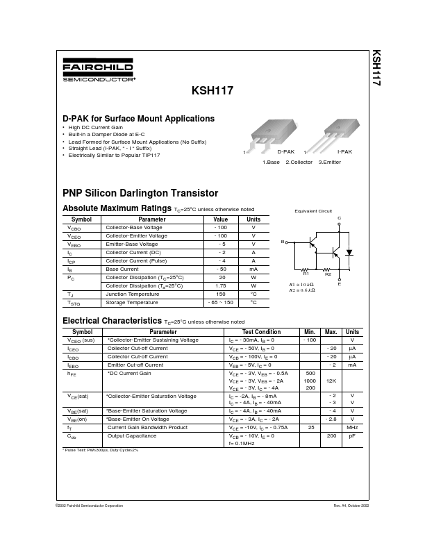
D-PAK for Surface Mount Applications
• • • • • High DC Current Gain Built-in a Damper Diode at E-C Lead F...
KSH117
KSH117
D-PAK for Surface Mount Applications
High DC Current Gain Built-in a Damper Diode at E-C Lead Formed for Surface Mount Applications (No Suffix) Straight Lead (I-PAK, “ - I “ Suffix) Electrically Similar to Popular TIP117
1
D-PAK 1.Base
1
I-PAK 3.Emitter
2.Collector
PNP Silicon Darlington Transistor
Absolute Maximum Ratings TC=25°C unless otherwise noted
Symbol VCBO VCEO VEBO IC ICP IB PC TJ TSTG Parameter Collector-Base
Voltage Collector-Emitter
Voltage Emitter-Base
Voltage Collector Current (DC) Collector Current (Pulse) Base Current Collector Dissipation (TC=25°C) Collector Dissipation (Ta=25°C) Junction Temperature Storage Temperature Value - 100 - 100 -5 -2 -4 - 50 20 1.75 150 - 65 ~ 150 Units V V V A A mA W W °C °C
R1 R2 E B Equivalent Circuit C
R 1 ≅ 10 k Ω R 2 ≅ 0.6 k Ω
Electrical Characteristics TC=25°C unless otherwise noted
Symbol VCEO (sus) ICEO ICBO IEBO hFE Parameter *Collector-Emitter Sustaining
Voltage Collector Cut-off Current Collector Cut-off Current Emitter Cut-off Current *DC Current Gain Test Condition IC = - 30mA, IB = 0 VCE = - 50V, IB = 0 VCB = - 100V, IE = 0 VEB = - 5V, IC = 0 VCE = - 3V, VEB = - 0.5A VCE = - 3V, VEB = - 2A VCE = - 3V, IC = - 4A IC = -2A, IB = - 8mA IC = - 4A, IB = - 40mA IC = - 4A, IB = - 40mA VCE = - 3A, IC = - 2A VCE = -10V, IC = - 0.75A VCB = - 10V, IE = 0 f= 0.1MHz 25 200 500 1000 200 Min. - 100 Max. - 20 - 20 -2 12K -2 -3 -4 - 2.8 V V V V MHz pF Units V µA µA mA
VCE(sat) VBE(sat) VBE(on) fT Cob
...