KSC2710
KSC2710
Low Frequency Power Amplifier
• Complement to KSA1150 • Collector Dissipation : PC=300mW
1
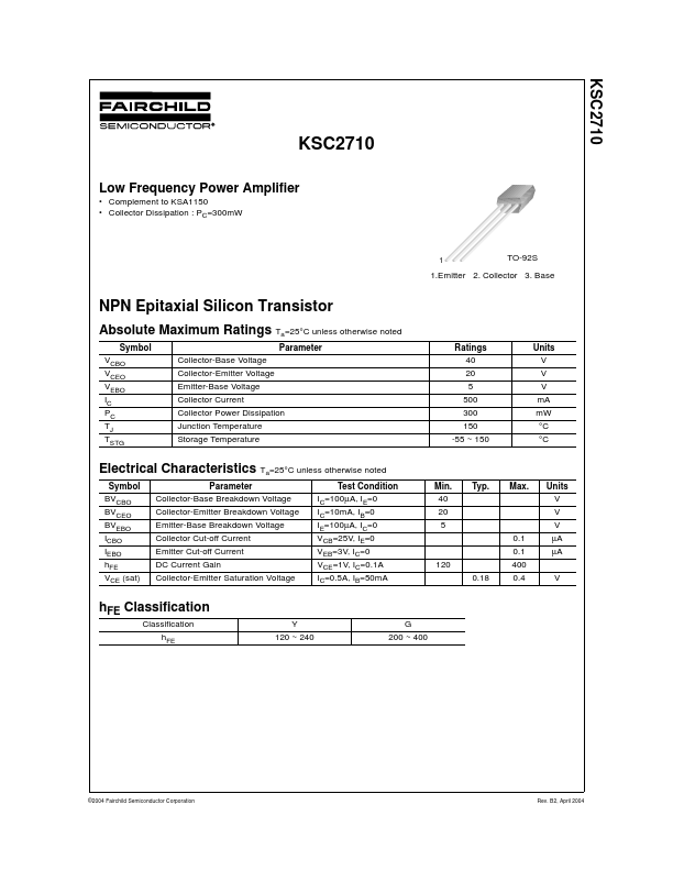
TO-92S
1....
KSC2710
KSC2710
Low Frequency Power Amplifier
Complement to KSA1150 Collector Dissipation : PC=300mW
1
TO-92S
1.Emitter 2. Collector 3. Base
NPN Epitaxial Silicon Transistor
Absolute Maximum Ratings Ta=25°C unless otherwise noted
Symbol VCBO VCEO VEBO IC PC TJ TSTG Parameter Collector-Base
Voltage Collector-Emitter
Voltage Emitter-Base
Voltage Collector Current Collector Power Dissipation Junction Temperature Storage Temperature Ratings 40 20 5 500 300 150 -55 ~ 150 Units V V V mA mW °C °C
Electrical Characteristics Ta=25°C unless otherwise noted
Symbol BVCBO BVCEO BVEBO ICBO IEBO hFE VCE (sat) Parameter Collector-Base Breakdown
Voltage Collector-Emitter Breakdown
Voltage Emitter-Base Breakdown
Voltage Collector Cut-off Current Emitter Cut-off Current DC Current Gain Collector-Emitter Saturation
Voltage Test Condition IC=100µA, IE=0 IC=10mA, IB=0 IE=100µA, IC=0 VCB=25V, IE=0 VEB=3V, IC=0 VCE=1V, IC=0.1A IC=0.5A, IB=50mA 120 0.18 Min. 40 20 5 0.1 0.1 400 0.4 V Typ. Max. Units V V V µA µA
hFE Classification
Classification hFE Y 120 ~ 240 G 200 ~ 400
©2004 Fairchild Semiconductor Corporation
Rev. B2, April 2004
KSC2710
Typical Characteristics
500
1000
IB = 2.0mA
VCE=1V
IC[mA], COLLECTOR CURRENT
400
IB = 1.8mA
hFE, DC CURRENT GAIN
IB = 1.6mA
300
IB = 1.4mA IB = 1.2mA
100
200
IB = 1.0mA IB = 0.8mA IB = 0.6mA
10
100
IB = 0.4mA IB = 0.2mA
0 0 2 4 6 8 10
1 1 10 100 1000
VCE[V], COLLECTOR-EMITTER
VOLTAGE
IC[mA], COLLECTOR CURRENT
Figure 1. Static Cha...