DatasheetsPDF.com
KBP207G
Part Number
KBP207G
Manufacturer
Surge Components
Description
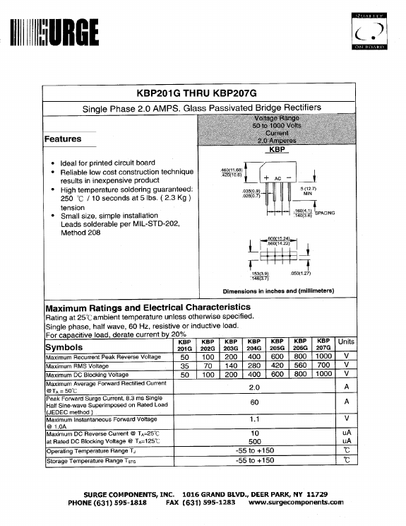
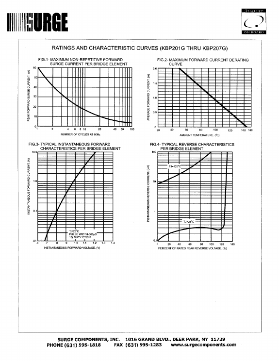
Single Phase 2.0 AMPS. Glass Passivated Bridge Rectifiers
Published
Apr 25, 2005
Datasheet
KBP207G
PDF File
Features
...
Similar Datasheet
KBP207G
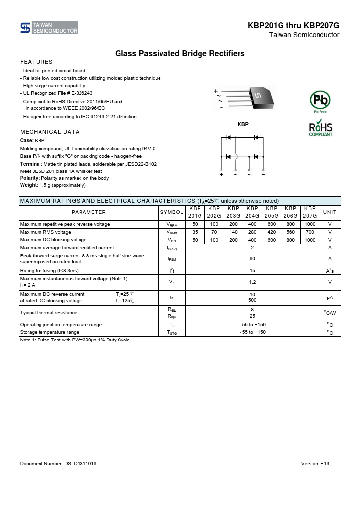
(KBP201G - KBP207G) Glass Passivated Bridge Rectifiers
(Taiwan Semiconductor Company)
KBP207G
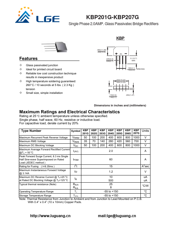
Glass Passivatec Bridge Rectifiers
(LGE)
KBP207G
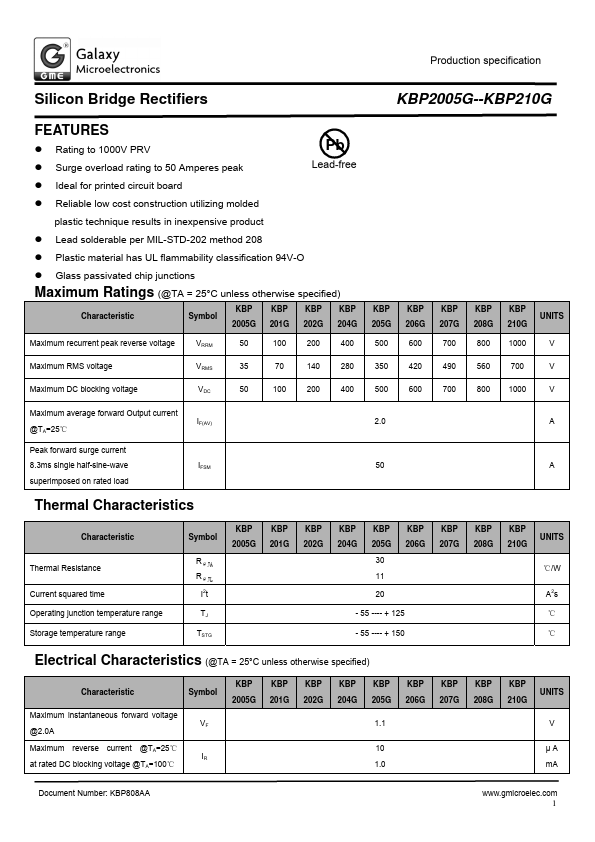
Silicon Bridge Rectifiers
(GME)
Since 2006. D4U Semicon,
Electronic Components Datasheet Search Site. (
Privacy Policy & Contact
)