W TE
POWER SEMICONDUCTORS
Features
! Diffused Junction ! Low Forward Voltage Drop ! High Current Capability ! High Relia...
W TE
POWER SEMICONDUCTORS
Features
! Diffused Junction ! Low Forward
Voltage Drop ! High Current Capability ! High Reliability ! High Surge Current Capability ! Ideal for Printed Circuit Boards ! UL Recognized File # E157705
Mechanical Data
! Case: Molded Plastic ! Terminals: Plated Leads Solderable per
MIL-STD-202, Method 208 ! Polarity: As Marked on Body ! Weight: 1.7 grams (approx.) ! Mounting Position: Any ! Marking: Type Number
KBP200 – KBP2010
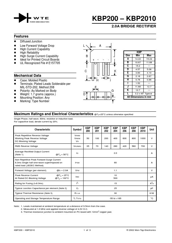
2.0A BRIDGE RECTIFIER
LA
BJ +~ ~ -
C
H E D
K I
G
KBP
Dim Min
Max
A 14.22 15.24
B 10.67 11.68
C 15.2
—
D 4.57 5.08
E 3.60 4.10
G 2.16 2.67
H 0.76 0.86
I 1.52 —
J 11.68 12.7
K 12.7
—
L 3.2 x 45° Typical
All Dimensions in mm
Maximum Ratings and Electrical Characteristics @TA=25°C unless otherwise specified
Single Phase, half wave, 60Hz, resistive or inductive load. For capacitive load, derate current by 20%.
Characteristic
Peak Repetitive Reverse
Voltage Working Peak Reverse
Voltage DC Blocking
Voltage
RMS Reverse
Voltage
Average Rectified Output Current (Note 1)
@TA = 50°C
Non-Repetitive Peak Forward Surge Current 8.3ms Single half sine-wave superimposed on rated load (JEDEC Method)
Forward
Voltage (per element)
Peak Reverse Current At Rated DC Blocking
Voltage
Rating for Fusing (t<8.3ms)
@IF = 2.0A
@TA = 25°C @TA = 100°C
Typical Junction Capacitance per element (Note 2)
Typical Thermal Resistance (Note 3)
Operating and Storage Temperature Range
Symbol VRRM VRWM VR VR(RMS)
IO
IFSM
VFM
IRM I2t Cj RJA...