|
Part Number
|
KBP005 |
|
Manufacturer
|
LGE |
|
Description
|
Silicon Bridge Rectifiers |
|
Published
|
Jul 14, 2016 |
|
Datasheet
|
 KBP005 PDF File KBP005 PDF File
|
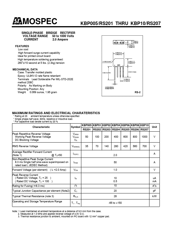
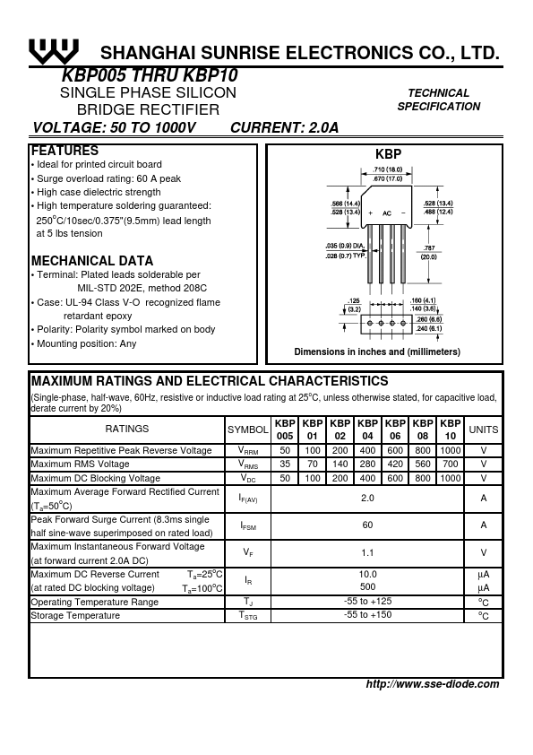
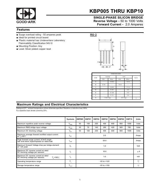
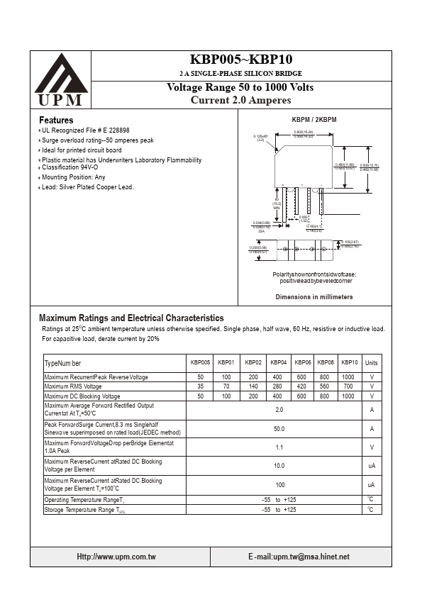
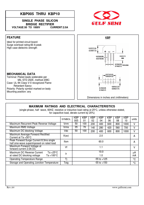
Features
Rating to 1000V PRV Surge overload rating to 50 Amperes peak Ideal for printed circuit board Reliable low cost construction utilizing molded plastic technique results in inexpensive product Lead solderable per MIL-STD-202 method 208 Plastic material ...
Similar Datasheet