DatasheetsPDF.com
J510
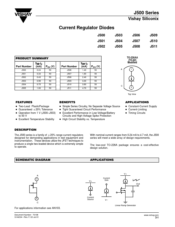
Current Regulator Diodes
Description
J500 Series Vishay Siliconix Current Regulator Diodes J500 J501 J502 PRODUCT SUMMARY Part Number J500 J501 J502 J503 J504 J505 J503 J504 J505 J506 J507 J508 TO-226AA (TO-92) Modified J509 J510 J511 Typ IF (mA) 0.24 0.33 0.43 0.56 0.75 1.00 POV (V) 50 50 50 50 50 50 Part Number J506 J507 J508 J509 J510 J511 Typ IF (mA) 1.40 1.80 2.40 3.00 3.60 4.70 P...
Vishay Siliconix
Download J510 Datasheet
Similar Datasheet
J510
n-channel JFET
- Siliconix
J510
CURRENT REGULATING DIODES
- Linear Integrated Systems
J510
Current Reg. Diode
- Micross
@ 2014 :: Datasheetspdf.com :: Semiconductors datasheet search & download site. (
Privacy Policy & Contact
)