DatasheetsPDF.com

J500 Datasheet

Part Number J500
Manufacturers Siliconix
Logo Siliconix
Description n-channel JFET
Datasheet J500 DatasheetJ500 Datasheet (PDF)

  J500   J500
n-channel JFETs current regulator diodes H Siliconix designed for. • • • Current Regulation Current Limiting • Biasing • Linear Ramp and Staircase - •o Generator 1ft -t ABSOLUTE MAXIMUM RATINGS (25°C) o Peak Operating Voltage . 50 V o1ft Forward Current .... 20 mA -t Reverse Current 50 mA Total Device Dissipation at 25°C Ambient (Derate 3.27 mW;oC) .. 360 mW Operating Temperature Range ... -55 to 135°C Storage Temperature Range -55 to 150°C Lead Temperature Range (1 /16" from case for 10 seconds) ....300°C Performance Curves NCL See Section 4 BENEFITS • Low Cost • Simple Two Lead Current Source • Simplifies Floating Current Sources No Power Supplies Required • Good Operating Current Tolerance ±20% TO-92 (MODIFIED) See Section 8 .ANODE ~ Plastic - CATHODE CO AC Bottom View c A ELECTRICAL CHARACTERISTICS (25°C unless otherwise noted) Charact.


Part Number J500
Manufacturers Linear Integrated Systems
Logo Linear Integrated Systems
Description CURRENT REGULATING DIODES
Datasheet J500 DatasheetJ500 Datasheet (PDF)

  J500   J500
J500 SERIES Linear Integrated Systems 
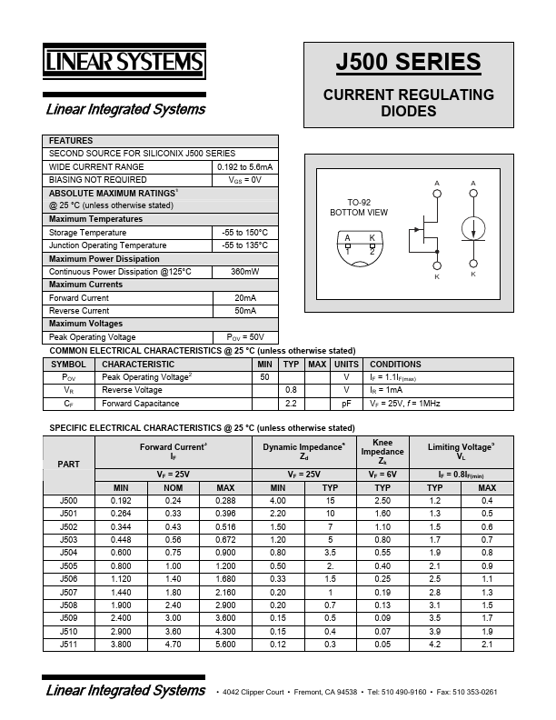
FEATURES SECOND SOURCE FOR SILICONIX J500 SERIES WIDE CURRENT RANGE BIASING NOT REQUIRED ABSOLUTE MAXIMUM RATINGS @ 25 °C (unless otherwise stated) Maximum Temperatures Storage Temperature Junction Operating Temperature Maximum Power Dissipation Continuous Power Dissipation @125°C Maximum Currents Forward Current Reverse Current Maximum Voltages Peak Operating Voltage SYMBOL POV VR CF CHARACTERISTIC Peak Operating Voltage2 Reverse Voltage Forward Capacitance POV = 50V MIN 50 0.8 2.2 TYP MAX UNITS V V pF CONDITIONS IF = 1.1IF(max) IR = 1mA VF = 25V, f = 1MHz COMMON ELECTRICAL CHARACTERISTICS @ 25 °C (unless otherwise stated) 20mA 50mA 360mW -55 to 150°C -.


Part Number J500
Manufacturers Vishay Siliconix
Logo Vishay Siliconix
Description Current Regulator Diodes
Datasheet J500 DatasheetJ500 Datasheet (PDF)

  J500   J500
J500 Series Vishay Siliconix Current Regulator Diodes J500 J501 J502 PRODUCT SUMMARY Part Number J500 J501 J502 J503 J504 J505 J503 J504 J505 J506 J507 J508 TO-226AA (TO-92) Modified J509 J510 J511 Typ IF (mA) 0.24 0.33 0.43 0.56 0.75 1.00 POV (V) 50 50 50 50 50 50 Part Number J506 J507 J508 J509 J510 J511 Typ IF (mA) 1.40 1.80 2.40 3.00 3.60 4.70 POV (V) 50 50 50 50 50 50 C 2 A 1 Top View FEATURES D Two-Lead PlasticPackage D Guaranteed "20% Tolerance D Operation from 1 V (J500–J503) to 50 V D Excellent Temperature Stability BENEFITS D Simple Series Circuitry, No Separate Voltage Source D Tight Guaranteed Circuit Performance D Excellent Performance in Low-Voltage/Battery Circuits.


Part Number J500
Manufacturers Micross
Logo Micross
Description Current Reg. Diode
Datasheet J500 DatasheetJ500 Datasheet (PDF)

  J500   J500
J500 Current Regulator Diode Linear Systems replaces discontinued Siliconix J500 The Linear Systems J500 is a ± 20% range current regulator The J500 is a ±20% range current regulator designed for demanding applications in test equipment and instrumentation. The J500 utilizes JFET techniques to produce a single two-leaded device which is extremely simple to operate. • • • • • • • • Two-Lead Plastic Package Guaranteed ±20% Tolerance Operation up to 50V Excellent Temperature Stability Simple Series Circuitry, No Separate Voltage Source Tight Guaranteed Circuit Performance Excellent Performance in Low-Voltage/Battery Circuits and High-Voltage Spike Protection High Circuit Stability vs. Temperat.


n-channel JFET

n-channel JFETs current regulator diodes H Siliconix designed for. • • • Current Regulation Current Limiting • Biasing • Linear Ramp and Staircase - •o Generator 1ft -t ABSOLUTE MAXIMUM RATINGS (25°C) o Peak Operating Voltage . 50 V o1ft Forward Current .... 20 mA -t Reverse Current 50 mA Total Device Dissipation at 25°C Ambient (Derate 3.27 mW;oC) .. 360 mW Operating Temperature Range ... -55 to 135°C Storage Temperature Range -55 to 150°C Lead Temperature Range (1 /16" from case for 10 seconds) ....300°C Performance Curves NCL See Section 4 BENEFITS • Low Cost • Simple Two Lead Current Source • Simplifies Floating Current Sources No Power Supplies Required • Good Operating Current Tolerance ±20% TO-92 (MODIFIED) See Section 8 .ANODE ~ Plastic - CATHODE CO AC Bottom View c A ELECTRICAL CHARACTERISTICS (25°C unless otherwise noted) Characteristic J500 J501 J502 J503 J504 J505 Unit Test Conditions ..2... -- 2 3 S T A 4 ,15- T I C 6 7 1- D I~ V N 9 IFI POV VL ZFI CF Forward Current (Note 1) Peak Operating Voltage (Notes 1 and 2) LImIting Voltage (Note 3) Small·Signal DynamIc Impedance (Note 1l Anode·Cathode CapacItance Min Nominal Max 0.192 0.240 0.288 0.264 0.330 0.396 0.344 0.430 0.516 0.448 0.560 0.672 0.600 0.750 0.900 0.800 1.000 1.200 mA VF = 25 V Min Max Typ Min Typ Typ 50 50 50 50 50 50 IF = 1.1 .


2019-09-22 : MPF111    J505    74ACT08    74AC08    VG-4231CA    VG-4232CA    IS64WV204816ALL    TPS7A60-Q1    PN4118A    LM2765   


@ 2014 :: Datasheetspdf.com ::
Semiconductors datasheet search & download site (Privacy Policy & Contact)