LowV-CE(sat) IGBT
www.DataSheet4U.com
Low VCE(sat) IGBT with Diode
ISOPLUS247TM
IXGR 60N60U1
VCES IC25 VCE(sat)
= = =
600 V 75 A 1.7 ...
Description
www.DataSheet4U.com
Low VCE(sat) IGBT with Diode
ISOPLUS247TM
IXGR 60N60U1
VCES IC25 VCE(sat)
= = =
600 V 75 A 1.7 V
(Electrically Isolated Back Surface)
Preliminary data
Symbol VCES VCGR VGES VGEM IC25 IC100 ICM
Test Conditions TJ = 25°C to 150°C TJ = 25°C to 150°C; RGE = 1 MW Continuous Transient TC = 25°C TC = 90°C TC = 25°C, 1 ms
Maximum Ratings 600 600 ±20 ±30 75 60 200 ICM = 100 300 -55 ..+ 150 150 -55...+ 150 V V V V A A A A W °C °C °C °C V g
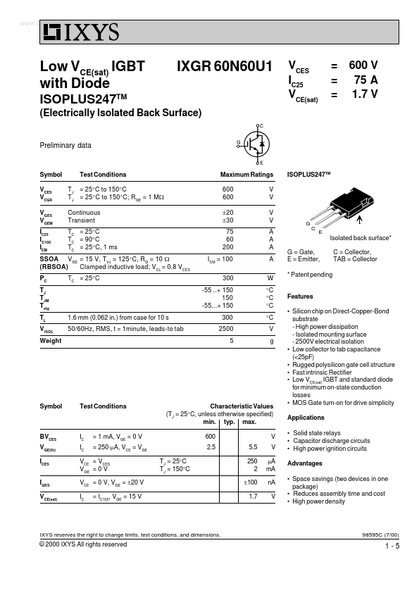
ISOPLUS247TM
G
C
E
Isolated back surface* G = Gate, E = Emitter, * Patent pending Features Silicon chip on Direct-Copper-Bond substrate - High power dissipation - Isolated mounting surface - 2500V electrical isolation Low collector to tab capacitance (<25pF) Rugged polysilicon gate cell structure Fast intrinsic Rectifier Low VCE(sat) IGBT and standard diode for minimum on-state conduction losses MOS Gate turn-on for drive simplicity Applications Solid state relays Capacitor discharge circuits High power ignition circuits Advantages Space savings (two devices in one package) Reduces assembly time and cost High power density C = Collector, TAB = Collector
SSOA VGE = 15 V, TVJ = 125°C, RG = 10 W (RBSOA) Clamped inductive load; VCL = 0.8 VCES PC TJ TJM Tstg TL V ISOL Weight 1.6 mm (0.062 in.) from case for 10 s 50/60Hz, RMS, t = 1minute, leads-to tab TC = 25°C
300 2500 5
Symbol
Test Conditions
Characteristic Values (TJ = 25°C, unless otherwise specified) min. typ. max. 600 2.5 TJ = 25°C TJ = ...
Similar Datasheet