Low VCE(sat) IGBT with Diode
Low VCE(sat) IGBT with Diode
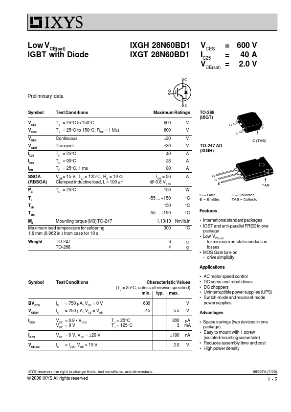
IXGH 28N60BD1 IXGT 28N60BD1
VCES = 600 V = 40 A IC25 VCE(sat) = 2.0 V
Preliminary data
S...
Description
Low VCE(sat) IGBT with Diode
IXGH 28N60BD1 IXGT 28N60BD1
VCES = 600 V = 40 A IC25 VCE(sat) = 2.0 V
Preliminary data
Symbol VCES VCGR VGES VGEM IC25 IC90 ICM SSOA (RBSOA) PC TJ TJM Tstg Md Mounting torque (M3) TO-247 Maximum lead temperature for soldering 1.6 mm (0.062 in.) from case for 10 s Weight TO-247 TO-268 Test Conditions T J = 25°C to 150°C T J = 25°C to 150°C; RGE = 1 MW Continuous Transient TC = 25°C TC = 90°C TC = 25°C, 1 ms VGE= 15 V, TVJ = 125°C, RG = 10 W Clamped inductive load, L = 100 mH TC = 25°C Maximum Ratings 600 600 ±20 ±30 40 28 80 ICM = 56 @ 0.8 VCES 150 -55 ... +150 150 -55 ... +150 V V V V A A A A W °C °C °C °C g g Features International standard packages IGBT and anti-parallel FRED in one package Low VCE(sat) - for minimum on-state conduction losses MOS Gate turn-on - drive simplicity Applications Symbol Test Conditions Characteristic Values (TJ = 25°C, unless otherwise specified) min. typ. max. 600 2.5 TJ = 25°C TJ = 125°C 5.5 200 3 ±100 2.0 V V mA mA nA V AC motor speed control DC servo and robot drives DC choppers Uninterruptible power supplies (UPS) Switch-mode and resonant-mode power supplies
G = Gate, E = Emitter, C = Collector, TAB = Collector G C E TAB
TO-268 (IXGT)
G E C (TAB)
TO-247 AD (IXGH)
1.13/10 Nm/lb.in. 300 6 4
BVCES VGE(th) ICES IGES VCE(sat)
IC IC
= 750 mA, VGE = 0 V = 250 mA, VCE = VGE
Advantages Space savings (two devices in one package) Easy to mount with 1 screw (isolated mounting screw hole) Re...
Similar Datasheet