HiPerFETTM Power MOSFETs
Single MOSFET Die
N-Channel Enhancement Mode Avalanche Rated, High dv/dt, Low trr
Preliminary d...
HiPerFETTM Power
MOSFETs
Single
MOSFET Die
N-Channel Enhancement Mode Avalanche Rated, High dv/dt, Low trr
Preliminary data sheet
Symbol VDSS VDGR VGS VGSM ID25 IDM IAR EAR EAS dv/dt PD TJ TJM Tstg TL VISOL Md Weight 1.6 mm (0.063 in.) from case for 10 s 50/60 Hz, RMS IISOL £ 1 mA t = 1 min t=1s Test Conditions T J = 25°C to 150°C T J = 25°C to 150°C; RGS = 1 MW Continuous Transient TC = 25°C TC = 25°C, pulse width limited by TJM TC = 25°C TC = 25°C TC = 25°C IS £ IDM, di/dt £ 100 A/ms, VDD £ VDSS T J £ 150°C, RG = 2 W TC = 25°C
IXFN 120N20
VDSS ID25
RDS(on)
= 200 V = 120 A = 17 mW
trr £ 250 ns
Maximum Ratings 200 200 ±20 ±30 120 480 120 64 3 5 600 -55 ... +150 150 -55 ... +150 2500 3000 V V V V A A A mJ J V/ns W °C °C °C °C V~ V~
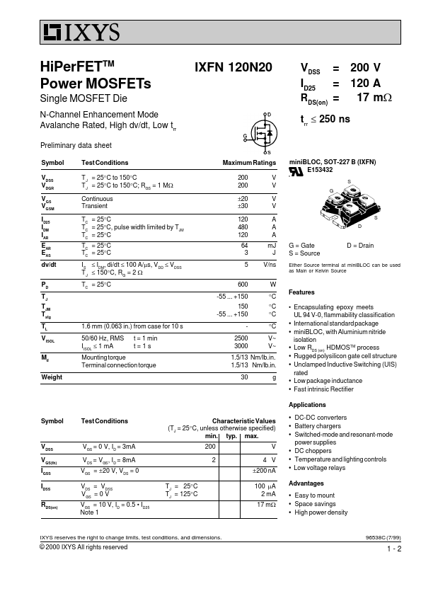
miniBLOC, SOT-227 B (IXFN) E153432
S G
S D
G = Gate S = Source
D = Drain
Either Source terminal at miniBLOC can be used as Main or Kelvin Source
Features Encapsulating epoxy meets UL 94 V-0, flammability classification International standard package miniBLOC, with Aluminium nitride isolation Low RDS (on) HDMOSTM process Rugged polysilicon gate cell structure Unclamped Inductive Switching (UIS) rated Low package inductance Fast intrinsic Rectifier Applications
Mounting torque Terminal connection torque
1.5/13 Nm/lb.in. 1.5/13 Nm/lb.in. 30 g
Symbol
Test Conditions
Characteristic Values (TJ = 25°C, unless otherwise specified) min. typ. max. 200 2 V 4 V ±200 nA TJ = 25°C TJ = 125°C 100 mA 2 mA 17 mW
DC-DC converters ...