Advanced Technical Information
HiPerFETTM Power MOSFETs
Q-Class
N-Channel Enhancement Mode Avalanche Rated, High dv/dt,...
Advanced Technical Information
HiPerFETTM Power
MOSFETs
Q-Class
N-Channel Enhancement Mode Avalanche Rated, High dv/dt, Low trr Low Gate Charge and Capacitances
Symbol VDSS VDGR VGS VGSM ID25 IDM IAR EAR EAS dv/dt PD TJ TJM Tstg TL Md Weight 1.6 mm (0.063 in) from case for 10 s Mounting torque TO-247 TO-264 TO-247 TO-264 TO-268 Test Conditions TJ = 25°C to 150°C TJ = 25°C to 150°C; RGS = 1 MW Continuous Transient TC = 25°C TC = 25°C, pulse width limited by TJM TC = 25°C TC = 25°C TC = 25°C IS £ IDM, di/dt £ 100 A/ms, VDD £ VDSS, TJ £ 150°C, RG = 2 W TC = 25°C
IXFH 60N25Q IXFK 60N25Q IXFT 60N25Q
VDSS ID25
RDS(on) trr
= 250 V = 60 A = 47 m W £ 250 ns
Maximum Ratings 250 250 ±20 ±30 60 240 60 45 1.5 5 360 -55 ... +150 150 -55 ... +150 300 V V V V A A A mJ J V/ns W °C °C °C °C
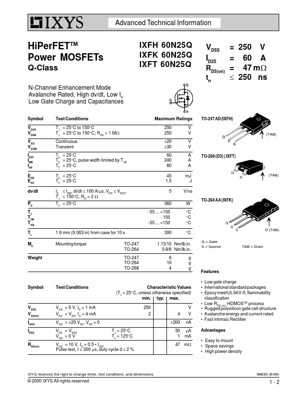
TO-247 AD (IXFH)
(TAB)
TO-268 (D3) ( IXFT)
G S
(TAB)
TO-264 AA (IXFK)
G D S
D (TAB)
1.13/10 Nm/lb.in. 0.9/6 Nm/lb.in. 6 10 4 g g g
G = Gate S = Source
TAB = Drain
Features Low gate charge International standard packages Epoxy meet UL 94 V-0, flammability classification Low RDS (on) HDMOSTM process Rugged polysilicon gate cell structure Avalanche energy and current rated Fast intrinsic Rectifier Advantages Easy to mount Space savings High power density
Symbol
Test Conditions
Characteristic Values (TJ = 25°C, unless otherwise specified) min. typ. max. 250 2 4 ±200 TJ = 25°C TJ = 125°C 50 1 V V nA mA mA
VDSS VGS(th) IGSS IDSS RDS(on)
VGS = 0 V, ID = 1 mA VDS = VGS, ID ...