TECHNICAL DATA
IW4518B
Dual Up-Counter
High-Voltage Silicon-Gate CMOS
The IW4518B Dual BCD Up-Counter consists two ide...
TECHNICAL DATA
IW4518B
Dual Up-Counter
High-
Voltage Silicon-Gate
CMOS
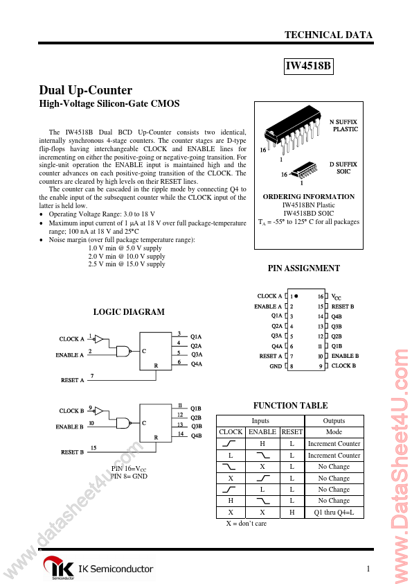
The IW4518B Dual BCD Up-Counter consists two identical, internally synchronous 4-stage counters. The counter stages are D-type flip-flops having interchangeable CLOCK and ENABLE lines for incrementing on either the positive-going or negative-going transition. For single-unit operation the ENABLE input is maintained high and the counter advances on each positive-going transition of the CLOCK. The counters are cleared by high levels on their RESET lines. The counter can be cascaded in the ripple mode by connecting Q4 to the enable input of the subsequent counter while the CLOCK input of the latter is held low. Operating
Voltage Range: 3.0 to 18 V Maximum input current of 1 µA at 18 V over full package-temperature range; 100 nA at 18 V and 25°C Noise margin (over full package temperature range): 1.0 V min @ 5.0 V supply 2.0 V min @ 10.0 V supply 2.5 V min @ 15.0 V supply
ORDERING INFORMATION IW4518BN Plastic IW4518BD SOIC TA = -55° to 125° C for all packages
PIN ASSIGNMENT
LOGIC DIAGRAM
FUNCTION TABLE
Inputs CLOCK ENABLE RESET H L X X L H X X X = don’t care L L L L L L H Outputs Mode Increment Counter Increment Counter No Change No Change No Change No Change Q1 thru Q4=L
w
w
w
.d
h s a t a
ee
. u t4
PIN 16=VCC PIN 8= GND
m o c
1
www.DataSheet4U.com
IW4518B
MAXIMUM RATINGS*
Symbol VCC VIN VOUT IIN PD PD Tstg TL
*
Parameter DC Supply
Voltage (Referenced to GND) DC Input
Voltage (Referen...