Previous Datasheet
Index
Next Data Sheet
PD - 9.767A
IRGPF50F
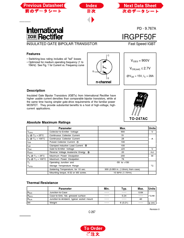
INSULATED GATE BIPOLAR TRANSISTOR
Features
• Switching...
Previous Datasheet
Index
Next Data Sheet
PD - 9.767A
IRGPF50F
INSULATED GATE BIPOLAR TRANSISTOR
Features
Switching-loss rating includes all "tail" losses Optimized for medium operating frequency (1 to 10kHz) See Fig. 1 for Current vs. Frequency curve
G E C
Fast Speed IGBT
VCES = 900V VCE(sat) ≤ 2.7V
@VGE = 15V, I C = 28A
n-channel
Description
Insulated Gate Bipolar Transistors (IGBTs) from International Rectifier have higher usable current densities than comparable bipolar transistors, while at the same time having simpler gate-drive requirements of the familiar power
MOSFET. They provide substantial benefits to a host of high-
voltage, highcurrent applications.
TO-247AC
Absolute Maximum Ratings
Parameter
VCES IC @ T C = 25°C IC @ T C = 100°C ICM ILM VGE EARV PD @ T C = 25°C PD @ T C = 100°C TJ TSTG Collector-to-Emitter
Voltage Continuous Collector Current Continuous Collector Current Pulsed Collector Current Clamped Inductive Load Current Gate-to-Emitter
Voltage Reverse
Voltage Avalanche Energy Maximum Power Dissipation Maximum Power Dissipation Operating Junction and Storage Temperature Range Soldering Temperature, for 10 sec. Mounting torque, 6-32 or M3 screw.
Max.
900 51 28 100 100 ±20 20 200 78 -55 to +150 300 (0.063 in. (1.6mm) from case) 10 lbfin (1.1Nm)
Units
V A
V mJ W
°C
Thermal Resistance
Parameter
RθJC RθCS RθJA Wt Junction-to-Case Case-to-Sink, flat, greased surface Junction-to-Ambient, typical socket mount Weight
Min.
---------------------
Ty...