www.DataSheet4U.com
IRFY240
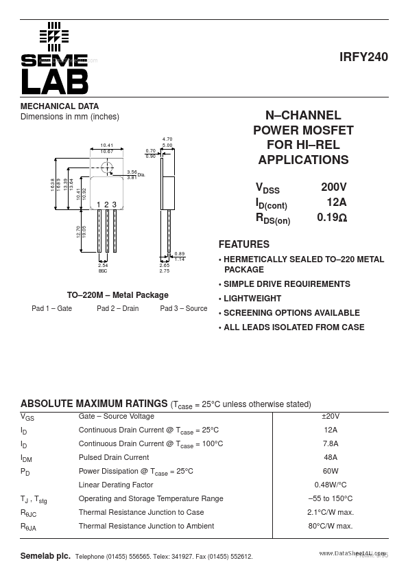
MECHANICAL DATA Dimensions in mm (inches)
4.70 5.00 0.70 0.90 3.56 Dia. 3.81
10.41 10.67
...
www.DataSheet4U.com
IRFY240
MECHANICAL DATA Dimensions in mm (inches)
4.70 5.00 0.70 0.90 3.56 Dia. 3.81
10.41 10.67
N–CHANNEL POWER
MOSFET FOR HI–REL APPLICATIONS
VDSS ID(cont) RDS(on)
FEATURES
0.89 1.14
16.38 16.89
13.39 13.64
1 2 3
12.70 19.05
200V 12A 0.19Ω
10.41 10.92
2.54 BSC
2.65 2.75
HERMETICALLY SEALED TO–220 METAL PACKAGE SIMPLE DRIVE REQUIREMENTS
TO–220M – Metal Package
Pad 1 – Gate Pad 2 – Drain Pad 3 – Source
LIGHTWEIGHT SCREENING OPTIONS AVAILABLE ALL LEADS ISOLATED FROM CASE
ABSOLUTE MAXIMUM RATINGS (Tcase = 25°C unless otherwise stated)
VGS ID ID IDM PD TJ , Tstg RθJC RθJA Gate – Source
Voltage Continuous Drain Current @ Tcase = 25°C Continuous Drain Current @ Tcase = 100°C Pulsed Drain Current Power Dissipation @ Tcase = 25°C Linear Derating Factor Operating and Storage Temperature Range Thermal Resistance Junction to Case Thermal Resistance Junction to Ambient ±20V 12A 7.8A 48A 60W 0.48W/°C –55 to 150°C 2.1°C/W max. 80°C/W max.
Semelab plc.
Telephone (01455) 556565. Telex: 341927. Fax (01455) 552612.
Prelim. 9/95
www.DataSheet4U.com
IRFY240
ELECTRICAL CHARACTERISTICS (TC = 25°C unless otherwise stated)
Parameter
BVDSS ∆TJ RDS(on) STATIC ELECTRICAL RATINGS Drain – Source Breakdown
Voltage Breakdown
Voltage Static Drain – Source On–State Resistance Forward Transconductance Zero Gate
Voltage Drain Current Forward Gate – Source Leakage Reverse Gate – Source Leakage DYNAMIC CHARACTERISTICS Input Capacitance Output Capacitance Revers...