Applications l High Efficiency Synchronous Rectification in
SMPS l Uninterruptible Power Supply l High Speed Power Switc...
Applications l High Efficiency Synchronous Rectification in
SMPS l Uninterruptible Power Supply l High Speed Power Switching l Hard Switched and High Frequency Circuits
Benefits l Improved Gate, Avalanche and Dynamic
dv/dt Ruggedness l Fully Characterized Capacitance and
Avalanche SOA l Enhanced body diode dV/dt and dI/dt
Capability
G
Absolute Maximum Ratings
Symbol
Parameter
ID @ TC = 25°C Continuous Drain Current, VGS @ 10V
ID @ TC = 100°C IDM PD @TC = 25°C
Continuous Drain Current, VGS @ 10V Pulsed Drain Current c Maximum Power Dissipation
Linear Derating Factor
VGS Gate-to-Source
Voltage
dv/dt
Peak Diode Recovery e
TJ TSTG
Operating Junction and Storage Temperature Range
Soldering Temperature, for 10 seconds
(1.6mm from case)
Avalanche Characteristics
EAS (Thermally limited) Single Pulse Avalanche Energy d IAR Avalanche Current c EAR Repetitive Avalanche Energy f
Thermal Resistance
Symbol
Parameter
RθJC Junction-to-Case j
RθCS
Case-to-Sink, Flat Greased Surface
RθJA Junction-to-Ambient ij
www.irf.com
PD - 97313
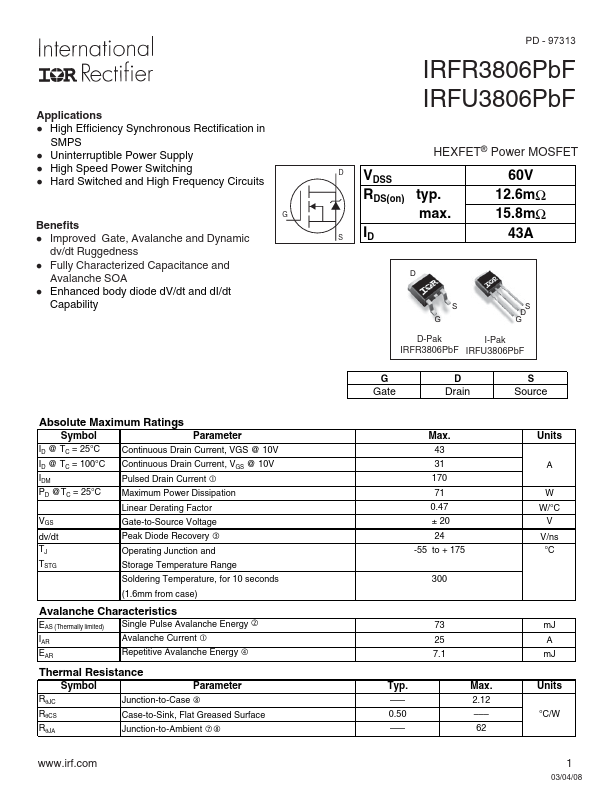
IRFR3806PbF IRFU3806PbF
HEXFET® Power
MOSFET
D VDSS RDS(on) typ. max.
S ID
60V 12.6mΩ 15.8mΩ
43A
D
S G
S D G
D-Pak
I-Pak
IRFR3806PbF IRFU3806PbF
G
Gate
D
Drain
S
Source
Max. 43 31 170 71 0.47 ± 20 24
-55 to + 175
300
Units
A
W W/°C
V V/ns °C
73 25 7.1
Typ. ––– 0.50 –––
Max. 2.12 ––– 62
mJ A mJ
Units °C/W
1
03/04/08
IRFR/U3806PbF
Static @ TJ = 25°C (unless otherwise specified)
Symbol
Parameter
Min. Typ. Max. Units
Co...