IL211AT/IL212AT/IL213AT
FEATURES
N EW
• High Current Transfer Ratio
IL211AT—20% Minimum IL212AT—50% Minimum IL213AT—10...
IL211AT/IL212AT/IL213AT
FEATURES
N EW
High Current Transfer Ratio
IL211AT—20% Minimum IL212AT—50% Minimum IL213AT—100% Minimum Isolation
Voltage, 2500 VACRMS Electrical Specifications Similar to Standard 6 Pin Coupler Industry Standard SOIC-8 Surface Mountable Package Standard Lead Spacing, .05" Available in Tape and Reel (suffix T) (Conforms to EIA Standard RS481A) Compatible with Dual Wave, Vapor Phase and IR Reflow Soldering Underwriters Lab File #E52744 (Code Letter P)
PHOTOTRANSISTOR SMALL OUTLINE SURFACE MOUNT OPTOCOUPLER
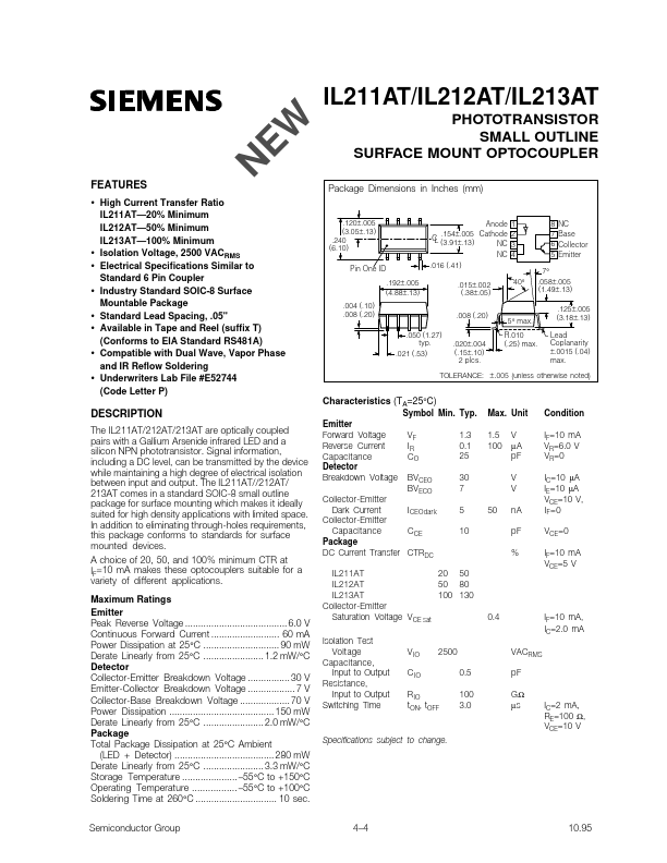
Package Dimensions in Inches (mm)
.120±.005 (3.05±.13) .240 (6.10) Pin One ID .192±.005 (4.88±.13) .004 (.10) .008 (.20)
Anode .154±.005 Cathode C L (3.91±.13) NC NC .016 (.41) .015±.002 (.38±.05) .008 (.20) .050 (1.27) typ. .021 (.53)
1 2 3 4 40°
8 7 6 5
NC Base Collector Emitter
7° .058±.005 (1.49±.13) .125±.005 (3.18±.13) Lead Coplanarity ±.0015 (.04) max.
5° max. R.010 (.25) max.
.020±.004 (.15±.10) 2 plcs.
TOLERANCE: ± .005 (unless otherwise noted)
Characteristics (TA=25°C)
Symbol Min. Typ. Emitter Forward
Voltage Reverse Current Capacitance Detector Breakdown
Voltage VF IR CO BVCEO BVECO 1.3 0.1 25 30 7 5 10 50 Max. Unit 1.5 100 V µA pF V V nA pF % Condition IF=10 mA VR=6.0 V VR=0 IC=10 µA IE=10 µA VCE=10 V, I F =0 VCE=0 IF=10 mA VCE=5 V
DESCRIPTION
The IL211AT/212AT/213AT are optically coupled pairs with a Gallium Arsenide infrared LED and a silicon NPN phototransistor. Signal information, including a DC level, can...