R SEMICONDUCTOR
HER601 THRU HER608
HIGH EFFICIENCY RECTIFIER
Reverse Voltage: 50 to 1000 Volts Forward Current:6.0Amper...
R SEMICONDUCTOR
HER601 THRU HER608
HIGH EFFICIENCY RECTIFIER
Reverse
Voltage: 50 to 1000 Volts Forward Current:6.0Amperes
FEATURES
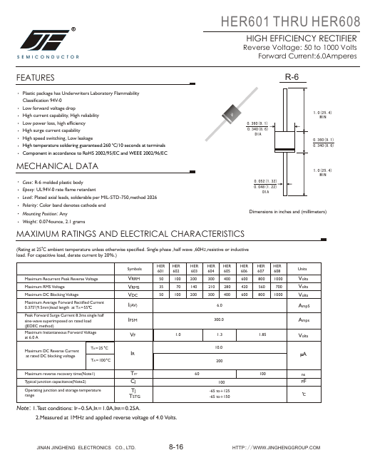
R-6
Plastic package has Underwriters Laboratory Flammability Classification 94V-0 Low forward
voltage drop High current capability, High reliability Low power loss, high efficiency High surge current capability High speed switching, Low leakage High temperature soldering guaranteed:260 C/10 seconds at terminals Component in accordance to RoHS 2002/95/EC and WEEE 2002/96/EC
JJF
0.360(9.1)
0.340(8.6) DIA
1.0(25.4) MIN
0.360(9.1) 0.340(8.6)
MECHANICAL DATA
Case: R-6 molded plastic body Epoxy: UL94V-0 rate flame retardant Lead: Plated axial leads, solderable per MIL-STD-750,method 2026 Polarity: Color band denotes cathode end Mounting Position: Any Weight: 0.074ounce, 2.1 grams
0.052(1.32) 0.048(1.22)
DIA
1.0(25.4) MIN
Dimensions in inches and (millimeters)
MAXIMUM RATINGS AND ELECTRICAL CHARACTERISTICS
(Rating at 25 C ambient temperature unless ot...