DatasheetsPDF.com
GP200
Part Number
GP200
Manufacturer
Goodpoly
Description
PPTC Thermistors
Published
Sep 12, 2013
Datasheet
GP200
PDF File
Features
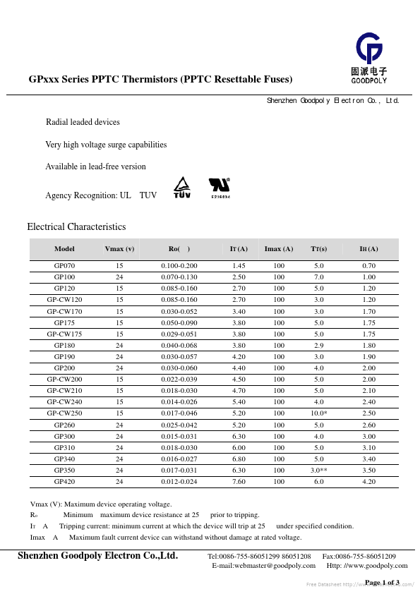
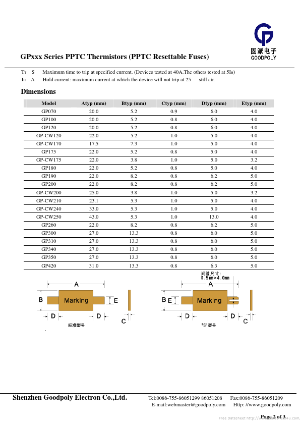
GPxxx Series PPTC Thermistors (PPTC Resettable Fuses) Shenzhen
Goodpoly
Electron Co., Ltd. ¡÷ ¡÷ ¡÷ Radial leaded devices Very high
voltage
surge capabilities Available in lead-free version ¡÷ Agency Recognition: UL¡¢ TUV Electrical Characteris...
Similar Datasheet
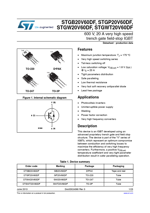
GP20V60DF
IGBT
(STMicroelectronics)
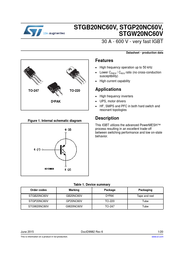
GP20NC60V
very fast IGBT
(STMicroelectronics)
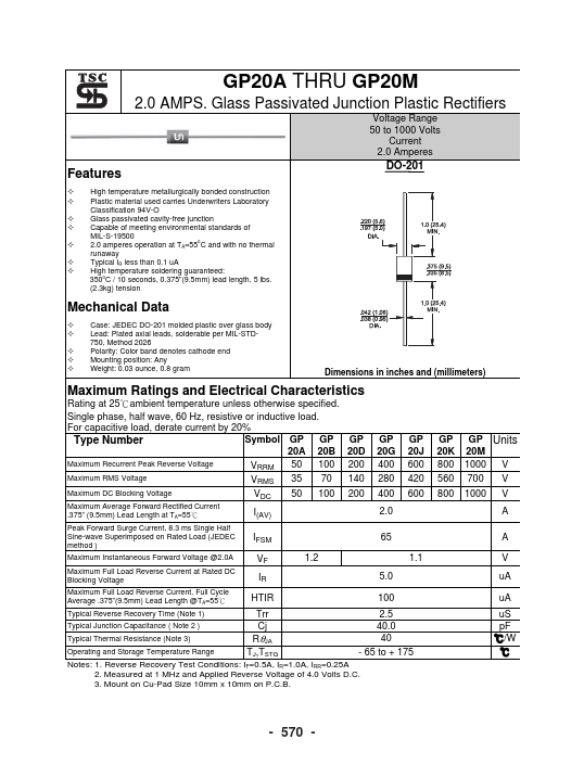
GP20M
2.0 AMPS. Glass Passivated Junction Plastic Rectifiers
(Taiwan Semiconductor)
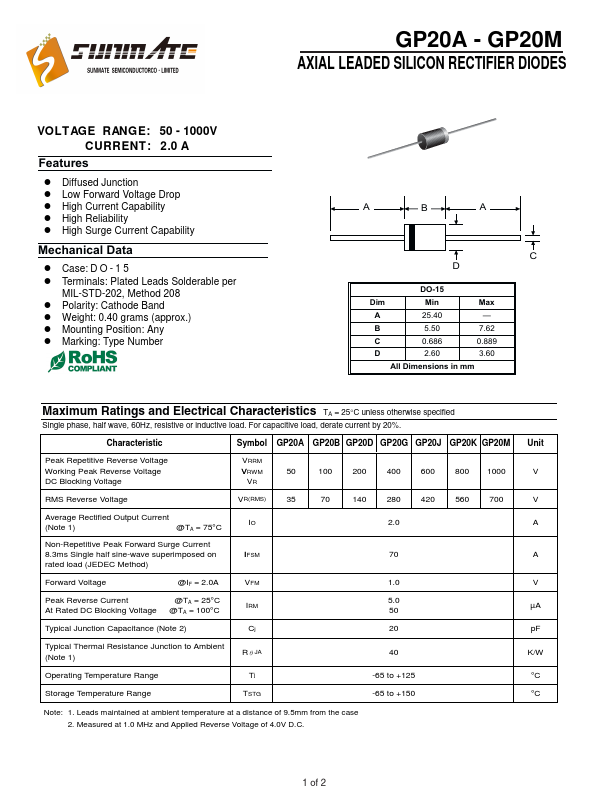
GP20M
AXIAL LEADED SILICON RECTIFIER DIODES
(Sunmate)
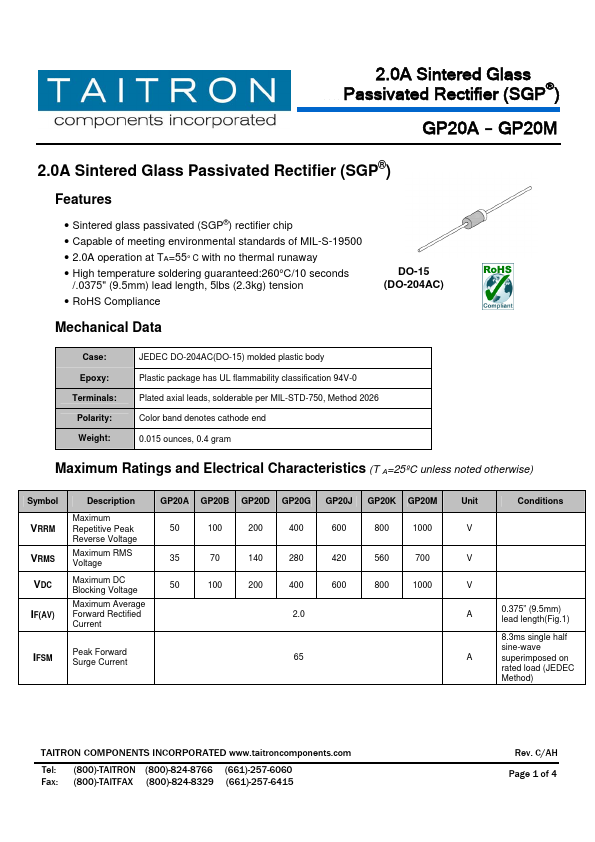
GP20M
2.0A Sintered Glass Passivated Rectifier
(TAITRON)
Since 2006. D4U Semicon,
Electronic Components Datasheet Search Site. (
Privacy Policy & Contact
)