FTP02N65 FTA02N65
N-Channel MOSFET
Applications:
• Adaptor • Charger • SMPS Standby Power • LCD Panel Power
Features:...
FTP02N65 FTA02N65
N-Channel
MOSFET
Applications:
Adaptor Charger SMPS Standby Power LCD Panel Power
Features:
RoHS Compliant Low ON Resistance Low Gate Charge Peak Current vs Pulse Width Curve Inductive Switching Curves
Ordering Information
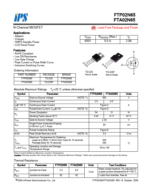
PART NUMBER FTP02N65 FTA02N65
PACKAGE TO-220 TO-220F
BRAND FTP02N65 FTA02N65
Pb Lead Free Package and Finish
VDSS 650V
RDS(ON) (Max.) 5.0 Ω
ID 2.0A
D
G DS
TO-220 Not to Scale
G DS
TO-220F Not to Scale
G
S
Absolute Maximum Ratings TC=25 oC unless otherwise specified
Symbol
Parameter
FTP02N65 FTA02N65
Units
VDSS ID ID@ 100 oC IDM
PD
Drain-to-Source
Voltage Continuous Drain Current Continuous Drain Current Pulsed Drain Current, VGS@ 10V Power Dissipation Derating Factor above 25 oC
(NOTE *1) (NOTE *2)
650 2.0 2.0*
Figure 3 Figure 6 54 21 0.43 0.17
V
A
W W/ oC
VGS
EAS
IAS dv/dt
Gate-to-Source
Voltage
Single Pulse Avalanche Engergy L=38 mH, ID=2.1 Amps Pulsed Avalanche Rating
Peak Diode Recovery dv/dt
(NOTE *3)
± 30 84
Figure 8 3.0
V mJ
V/ ns
TL TPKG TJ and TSTG
Maximum Temperature for Soldering Leads at 0.063in (1.6mm) from Case for 10 seconds Package Body for 10 seconds
Operating Junction and Storage Temperature Range
300 260
-55 to 150
oC
*Drain Current limited by Maximum Junction Temperature. Caution: Stresses greater than those listed in the “Absolute Maximum Ratings” Table may cause permanent damage to the device.
Thermal Resistance
Symbol
Parameter
FTP02N65
RθJC
Junction-to-Case
...