www.datasheet4u.com
FS08...I
STANDARD SCR
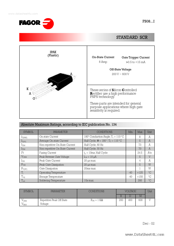
IPAK (Plastic)
On-State Current 8 Amp
Gate Trigger Current >0.5 to <15 mA...
www.datasheet4u.com
FS08...I
STANDARD SCR
IPAK (Plastic)
On-State Current 8 Amp
Gate Trigger Current >0.5 to <15 mA
Off-State
Voltage
A
200 V ÷ 600 V
K A G
These series of Silicon Controlled R ectifier use a high performance PNPN technology. These parts are intended for general purpose applications where high gate sensitivity is required.
Absolute Maximum Ratings, according to IEC publication No. 134
SYMBOL PARAMETER On-state Current Average On-state Current Non-repetitive On-State Current Non-repetitive On-State Current Fusing Current Peak Reverse Gate
Voltage Peak Gate Current Peak Gate Dissipation Gate Dissipation Operating Temperature Storage Temperature Soldering Temperature CONDITIONS 180º Conduction Angle, Tc = 110 ºC Half Cycle, Θ = 180 º, TC = 110 ºC Half Cycle, 60 Hz Half Cycle, 50 Hz tp = 10ms, Half Cycle IGR = 10 µA 20 µs max. 20 µs max. 20ms max. -40 -40 10s max. Min. Max. 8 5 73 70 24.5 5 4 5 1 +125 +150 260 Unit A A A A A 2s V A W W ºC ºC ºC
IT(RMS) IT(AV) ITSM ITSM I2t VGRM IGM PGM PG(AV) Tj Tstg Tsld
SYMBOL
PARAMETER Repetitive Peak Off State
Voltage
CONDITIONS RGK = 1 KΩ B 200
VOLTAGE D 400 M 600
Unit V
VDRM VRRM
Dec - 02
www.datasheet4u.com
FS08...I
STANDARD SCR
Electrical Characteristics
SYMBOL PARAMETER Gate Trigger Current Off-State Leakage Current On-state
Voltage Gate Trigger
Voltage Gate Non Trigger
Voltage Holding Current Latching Current Critical Rate of
Voltage Rise CONDITIONS VD = 12 VDC , RL = 33Ω. Tj = 25 ºC MIN MAX MAX MAX...