ELM312 Stepper Motor Controller
Description
The ELM312 is an interface circuit for use between high speed logic and fou...
ELM312 Stepper Motor Controller
Description
The ELM312 is an interface circuit for use between high speed logic and four phase stepper motor driver circuits. All of the logic required to provide stepping in two directions is contained in this one 8 pin package.
This circuit supports only the half-step mode of operation. This mode provides eight distinct phase control output signals for driving a variety of motors. For dual mode operation, the ELM310 should be considered.
The ELM312 can be controlled by a wide variety of circuits, due to its fully static operation. In addition to using high speed microprocessor control, suitably debounced mechanical switches or continuously running oscillator circuits could also be used.
Features
Low power
CMOS design - typically 1mA at 5V Wide supply range - 3.0 to 5.5 volt operation Two inputs control Half step motion No external timing components Completely static operation - will maintain a step
position indefinitely High current drive outputs - up to 25 mA Very high speed - up to 25000 steps per second
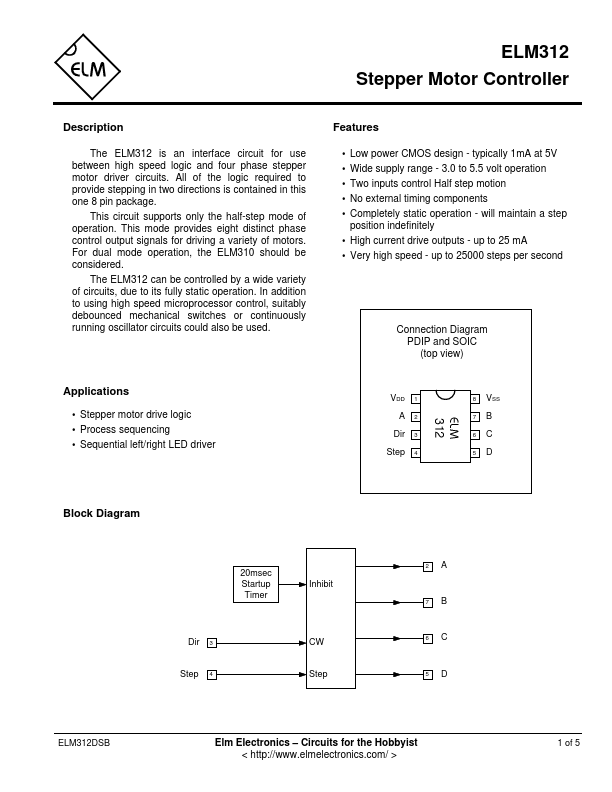
Connection Diagram PDIP and SOIC (top view)
Applications
Stepper motor drive logic Process sequencing Sequential left/right LED driver
VDD 1 A2
Dir 3 Step 4
8 VSS 7B 6C 5D
Block Diagram
20msec Startup Timer
Inhibit
Dir 3 Step 4
CW Step
2A 7B 6C 5D
ELM312DSB
Elm Electronics – Circuits for the Hobbyist < http://www.elmelectronics.com/ >
1 of 5
ELM312
Pin Descriptions
VDD (pin 1) This pin is the positive sup...