www.DataSheet4U.com
EDE1200 Unipolar Stepper Motor IC
EDE1200
Phase Three Drive Signal Phase Four Drive Signal Connect...
www.DataSheet4U.com
EDE1200 Unipolar Stepper Motor IC
EDE1200
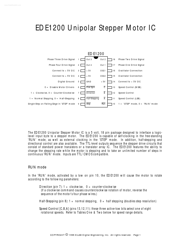
Phase Three Drive Signal Phase Four Drive Signal Connect to +5V DC Connect to +5V DC Digital Ground 0 = Disable Motor Drivers 1 = Clockwise, 0 = Counter-Clockwise 1 = Normal Stepping, 0 = Half-Stepping Single-Step on Falling Edge in 'STEP' mode
1 2 3 4 5 6 7 8 9 Out 3 Out 4 +5V +5V GND Free Spin Direction Half-Stepping Step Out 2 Out 1 OSC1 OSC2 +5V C B A Run 18 17 16 15 14 13 12 11 10
Phase Two Drive Signal Phase One Drive Signal Oscillator Connection Oscillator Connection Connect to +5V DC Speed Control (MSB) Speed Control Speed Control (LSB) 1 = 'STEP' mode, 0 = 'RUN' mode
The EDE1200 Unipolar Stepper Motor IC is a 5 volt, 18 pin package designed to interface a logiclevel input byte to a stepper motor. The EDE1200 is capable of self-clocking in the free-standing 'RUN' mode, as well as external clocking in the 'STEP' mode. In addition, half-stepping and directional control are also available. The TTL-level outputs sequence the stepper drive circuits that consist of standard power transistors or a transistor array IC. The EDE1200 features the ability to change the stepping rate while the motor is stepping and to take an unlimited number of steps in continuous 'RUN' mode. Inputs are TTL/
CMOS compatible.
RUN mode
In the 'RUN' mode, activated by a low on pin 10, the EDE1200 will cause the motor to rotate according to the following parameters: Direction (pin 7): 1 = clockwise, 0 = counter-clockwise (If a clockwi...