54LS11 DM54LS11 DM74LS11 Triple 3-Input AND Gates
June 1989
54LS11 DM54LS11 DM74LS11 Triple 3-Input AND Gates
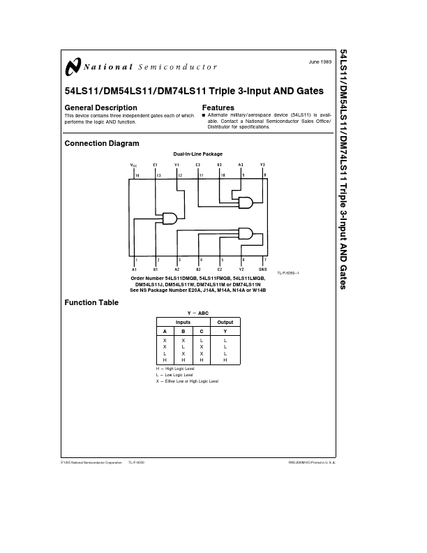
General Description
This device contains three independent gates each of which performs the logic AND function
Features
Y
Alternate military aerospace device (54LS11) is available Contact a National Semiconductor Sales Office Distributor for spec...