February 2005
®
AS7C3364FT32B AS7C3364FT36B
3.3V 64K × 32/36 Flow Through Synchronous SRAM
Features
• • • • • • • Orga...
February 2005
®
AS7C3364FT32B AS7C3364FT36B
3.3V 64K × 32/36 Flow Through Synchronous SRAM
Features
Organization: 65,536 words × 32 or 36 bits Fast clock to data access: 6.5/7.5/8.0/10.0 ns Fast OE access time: 3.5/4.0 ns Fully synchronous flow through operation Asynchronous output enable control Available in 100-pin TQFP package Individual byte write and Global write
Multiple chip enables for easy expansion 3.3V core power supply 2.5V or 3.3V I/O operation with separate VDDQ Linear or interleaved burst control Snooze mode for reduced power standby Common data inputs and data outputs
www.DataSheet4U.com
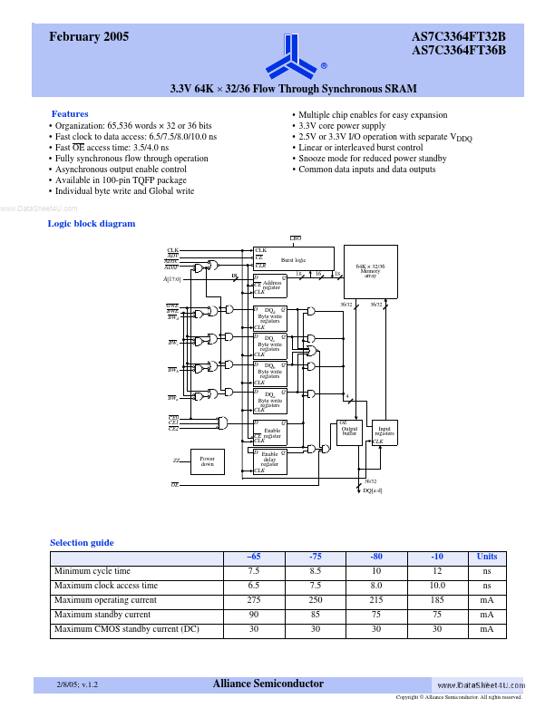
Logic block diagram
LBO CLK ADV ADSC ADSP A[17:0] 18 Q0 Burst logic Q1 18 D Q CE Address register CLK D DQd Q Byte write registers CLK D DQ Q c Byte write registers CLK D DQb Q Byte write registers CLK D BWa CE0 CE1 CE2 DQa Q Byte write registers CLK D Enable CE register CLK Power down D Enable Q delay register CLK 36/32 DQ[a:d] Q 4 CLK CE CLR
16
18
64K × 32/36 Memory array
GWE BWE BWd
36/32
36/32
BWc
BWb
OE Output buffer
Input registers CLK
ZZ
OE
Selection guide
–65 Minimum cycle time Maximum clock access time Maximum operating current Maximum standby current Maximum
CMOS standby current (DC) 7.5 6.5 275 90 30 -75 8.5 7.5 250 85 30 -80 10 8.0 215 75 30 -10 12 10.0 185 75 30 Units ns ns mA mA mA
2/8/05; v.1.2
Alliance Semiconductor
P. 1 of 19
Copyright © Alliance Semiconductor. All rights reserved.
AS7C3364FT32B AS7C3364FT36B
®
...