DatasheetsPDF.com

5021D-B11

EMCORE

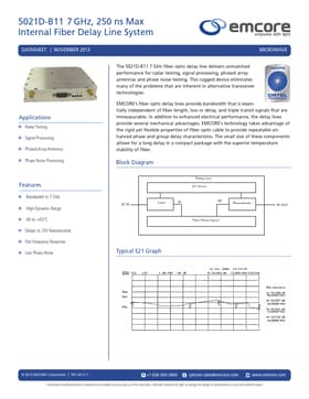
7GHz 250ns Max Internal Fiber Delay Line System

5021D-B11 7 GHz, 250 ns Max Internal Fiber Delay Line System DATASHEET | NOVEMBER 2013 MICROWAVE Applications „ Radar...


EMCORE

5021D-B11

File Download Download 5021D-B11 Datasheet


Description
5021D-B11 7 GHz, 250 ns Max Internal Fiber Delay Line System DATASHEET | NOVEMBER 2013 MICROWAVE Applications „ Radar Testing „ Signal Processing „ Phased Array Antennas „ Phase Noise Processing The 5021D-B11 7 GHz fiber optic delay line delivers unmatched performance for radar testing, signal processing, phased array antennas and phase noise testing. This rugged device eliminates many of the problems that are inherent in alternative transceiver technologies. EMCORE’s fiber optic delay lines provide bandwidth that is essentially independent of fiber length, loss or delay, and triple transit signals that are immeasurable. In addition to enhanced electrical performance, the delay lines provide several mechanical advantages. EMCORE’s technology takes advantage of the rigid yet flexible properties of fiber optic cable to provide repeatable enhanced phase and group delay characteristics. The small size of these components allows for a long delay in a compact package with the superior temperature stability of fiber. Block Diagram „„ „ „ „ „ „ „ „ „ Features „ Bandwidth to 7 GHz „ High-Dynamic-Range „ -40 to +65°C „ Delays to 250 Nanoseconds „ Flat Frequency Response „ Low Phase Noise RF IN Delay Line DC Driver Laser PL PR Photodiode Fiber Delay Spool RF OUT Typical S21 Graph © 2013 EMCORE Corporation | REV 2013.11 +1 626-293-3400 [email protected] www.emcore.com Information contained herein is deemed to be reliable and accurate as of the issue date. EMCORE...


Similar Datasheet


@ 2014 :: Datasheetspdf.com :: Semiconductors datasheet search & download site. (Privacy Policy & Contact)