DatasheetsPDF.com

1N4001 Datasheet

Part Number 1N4001
Manufacturers ON Semiconductor
Logo ON Semiconductor
Description Axial Lead Standard Recovery Rectifiers
Datasheet 1N4001 Datasheet1N4001 Datasheet (PDF)

  1N4001   1N4001
DATA SHEET www.onsemi.com Axial-Lead Glass Passivated Standard Recovery Rectifiers LEAD MOUNTED RECTIFIERS 50−1000 VOLTS DIFFUSED JUNCTION 1N4001, 1N4002, 1N4003, 1N4004, 1N4005, 1N4006, 1N4007 This data sheet provides information on subminiature size, axial lead mounted rectifiers for general−purpose low−power applications. Features • Shipped in Plastic Bags, 1000 per bag • Available Tape and Reeled, 5000 per reel, by adding a “RL” suffix to the part number • Available in Fan−Fold Packaging, 3000 per box, by adding a “FF” suffix to the part number • Pb−Free Packages are Available Mechanical Characteristics • Case: Epoxy, Molded • Weight: 0.4 gram (approximately) • Finish: All External Surfaces Corrosion Resistant and Terminal Leads are Readily Solderable • Lead and Mounting Surface Temperature for Soldering Purposes: 260°C Max. for 10 Seconds, 1/16 in. from case • Polarity: Cathode Indicated by Polarity Band *For additional information on our Pb−Free strategy and soldering details,.


Part Number 1N4001
Manufacturers Fairchild Semiconductor
Logo Fairchild Semiconductor
Description General Purpose Rectifiers
Datasheet 1N4001 Datasheet1N4001 Datasheet (PDF)

  1N4001   1N4001
1N4001 - 1N4007 — General-Purpose Rectifiers November 2014 1N4001 - 1N4007 General-Purpose Rectifiers Features • Low Forward Voltage Drop • High Surge Current Capability Ordering Information Part Number 1N4001 1N4002 1N4003 1N4004 1N4005 1N4006 1N4007 Top Mark 1N4001 1N4002 1N4003 1N4004 1N4005 1N4006 1N4007 DO-41 COLOR BAND DENOTES CATHODE Package DO-204AL (DO-41) DO-204AL (DO-41) DO-204AL (DO-41) DO-204AL (DO-41) DO-204AL (DO-41) DO-204AL (DO-41) DO-204AL (DO-41) Packing Method Tape and Reel Tape and Reel Tape and Reel Tape and Reel Tape and Reel Tape and Reel Tape and Reel Absolute Maximum Ratings Stresses exceeding the absolute maximum ratings may damage the device. The device .


Part Number 1N4001
Manufacturers MCC
Logo MCC
Description 1.0 Amp Rectifier
Datasheet 1N4001 Datasheet1N4001 Datasheet (PDF)

  1N4001   1N4001
1N4001 THRU 1N4007 Features • Low Current Leakage • Epoxy Meets UL 94 V-0 Flammability Rating • Halogen Free Available Upon Request By Adding Suffix "-HF" • Lead Free Finish/RoHS Compliant (Note1) ("P"Suffix Designates Compliant. See Ordering Information) Maximum Ratings • Operating Junction Temperature Range: -55⁰C to +150⁰C • Storage Temperature Range: -55⁰C to +150⁰C • Typical Thermal Resistance: 35⁰C/W Junction to Case (Note 2) • Typical Thermal Resistance: 25⁰C/W Junction to Lead(Note 2) • Typical Thermal Resistance: 50⁰C/W Junction to Ambient(Note 2) MCC Part Number 1N4001 1N4002 1N4003 1N4004 1N4005 1N4006 1N4007 Device Marking 1N4001 1N4002 1N4003 1N4004 1N4005 1N4006 1N4007 Maxi.


Part Number 1N4001
Manufacturers WON-TOP
Logo WON-TOP
Description 1.0A STANDARD DIODE
Datasheet 1N4001 Datasheet1N4001 Datasheet (PDF)

  1N4001   1N4001
® WON-TOP ELECTRONICS Features  Diffused Junction  Low Forward Voltage Drop  High Current Capability  High Reliability  High Surge Current Capability 1N4001 – 1N4007 1.0A STANDARD DIODE Pb A B A Mechanical Data  Case: DO-41, Molded Plastic  Terminals: Plated Leads Solderable per MIL-STD-202, Method 208  Polarity: Cathode Band  Weight: 0.35 grams (approx.)  Mounting Position: Any  Marking: Type Number  Lead Free: For RoHS / Lead Free Version, Add “-LF” Suffix to Part Number, See Page 4 C D DO-41 Dim Min Max A 25.4 — B 4.06 5.21 C 0.71 0.864 D 2.00 2.72 All Dimensions in mm Maximum Ratings and Electrical Characteristics @TA=25°C unless otherwise specified Si.


Part Number 1N4001
Manufacturers Vishay Siliconix
Logo Vishay Siliconix
Description 1.0A RECTIFIER
Datasheet 1N4001 Datasheet1N4001 Datasheet (PDF)

  1N4001   1N4001
1N4001, 1N4002, 1N4003, 1N4004, 1N4005, 1N4006, 1N4007 www.vishay.com Vishay General Semiconductor General Purpose Plastic Rectifier DO-41 (DO-204AL) FEATURES • Low forward voltage drop • Low leakage current • High forward surge capability • Solder dip 275 °C max. 10 s, per JESD 22-B106 • Material categorization: for definitions of compliance please see www.vishay.com/doc?99912 PRIMARY CHARACTERISTICS IF(AV) VRRM 1.0 A 50 V, 100 V, 200 V, 400 V, 600 V, 800 V, 1000 V IFSM (8.3 ms sine-wave) IFSM (square wave tp = 1 ms) VF IR TJ max. Package 30 A 45 A 1.1 V 5.0 μA 150 °C DO-41 (DO-204AL) Circuit configuration Single TYPICAL APPLICATIONS For use in general purpose rectification of .


Part Number 1N4001
Manufacturers Diodes
Logo Diodes
Description 1.0A RECTIFIER
Datasheet 1N4001 Datasheet1N4001 Datasheet (PDF)

  1N4001   1N4001
Pb 1N4001 – 1N4007 THE 1N4001-1N4007 IS NOT RECOMMENDED FOR NEW DESIGNS. PLEASE USE THE 1N4007G_HF. 1.0A RECTIFIER Features  Diffused Junction  High Current Capability and Low-Forward Voltage Drop  Surge Overload Rating to 30A Peak  Low Reverse Leakage Current  Lead-Free Finish; RoHS Compliant (Notes 1 & 2)  For automotive applications requiring specific change control (i.e. parts qualified to AEC-Q100/101/104/200, PPAP capable, and manufactured in IATF 16949 certified facilities), please contact us or your local Diodes representative. https://www.diodes.com/quality/product-definitions/ Mechanical Data  Package: DO-41  Package Material: Molded Plastic. UL Flammability Classifica.


Axial Lead Standard Recovery Rectifiers

DATA SHEET www.onsemi.com Axial-Lead Glass Passivated Standard Recovery Rectifiers LEAD MOUNTED RECTIFIERS 50−1000 VOLTS DIFFUSED JUNCTION 1N4001, 1N4002, 1N4003, 1N4004, 1N4005, 1N4006, 1N4007 This data sheet provides information on subminiature size, axial lead mounted rectifiers for general−purpose low−power applications. Features • Shipped in Plastic Bags, 1000 per bag • Available Tape and Reeled, 5000 per reel, by adding a “RL” suffix to the part number • Available in Fan−Fold Packaging, 3000 per box, by adding a “FF” suffix to the part number • Pb−Free Packages are Available Mechanical Characteristics • Case: Epoxy, Molded • Weight: 0.4 gram (approximately) • Finish: All External Surfaces Corrosion Resistant and Terminal Leads are Readily Solderable • Lead and Mounting Surface Temperature for Soldering Purposes: 260°C Max. for 10 Seconds, 1/16 in. from case • Polarity: Cathode Indicated by Polarity Band *For additional information on our Pb−Free strategy and soldering details, please download the onsemi Soldering and Mounting Techniques Reference Manual, SOLDERRM/D. 
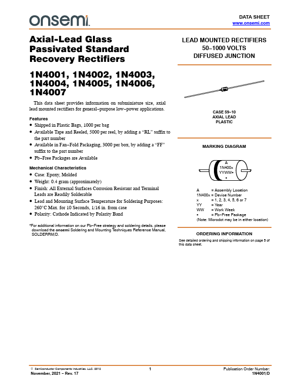
CASE 59−10 AXIAL LEAD PLASTIC MARKING DIAGRAM A 1N400x YYWWG G A = Assembly Location 1N400x = Device Number x = 1, 2, 3, 4, 5, 6 or 7 YY = Year WW = Work Week G = Pb−Free Package (Note: Microdot may be in either location) ORDERING INFORMATION See detailed ordering and shipping information on page 5 of this data sheet. © Semiconductor Components Industries, LLC, 2012 1 November, 2021 − Rev.


2005-10-05 : MC35181    MC35182    MC35184    MC33181    MC33182    MC33184    MSC1210    AMC7110    AMC7111    AMC7113   


@ 2014 :: Datasheetspdf.com ::
Semiconductors datasheet search & download site (Privacy Policy & Contact)